
Camera fixing structure and wrist equipment

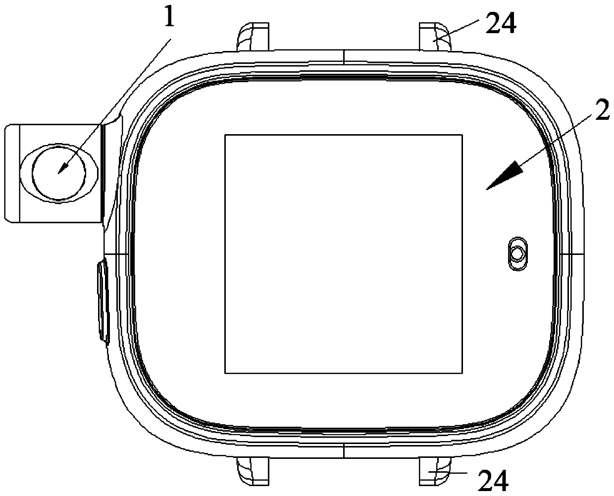
A fixed structure and camera technology, applied in mechanical equipment, image communication, television, etc., can solve problems such as small battery capacity, affecting user experience, and inability to use camera components, so as to optimize user experience, reduce occupation, and have a wide range of options Effect

Active Publication Date: 2020-04-10
GEER TECH CO LTD
View PDF8 Cites 2 Cited by
  • Summary
  • Abstract
  • Description
  • Claims
  • Application Information

AI Technical Summary

Problems solved by technology

Because the camera component needs to occupy a large space inside the main body of the watch case, it affects the expansion of other functions of the wrist-worn device, resulting in a small battery capacity, which affects the battery life of the whole machine. Due to the limited space, it is impossible to use higher definition and resolution. The camera component affects the user experience

Method used


Image

  • Camera fixing structure and wrist equipment
  • Camera fixing structure and wrist equipment
  • Camera fixing structure and wrist equipment

Examples


Embodiment Construction

[0030] The following will clearly and completely describe the technical solutions in the embodiments of the present invention with reference to the accompanying drawings in the embodiments of the present invention. Obviously, the described embodiments are only some, not all, embodiments of the present invention. Based on the embodiments of the present invention, all other embodiments obtained by persons of ordinary skill in the art without making creative efforts belong to the protection scope of the present invention.

[0031] The core of the present invention is to provide a camera fixing structure, which can reduce the occupation of the internal space of the watch case body by the camera assembly. Another core of the present invention is to provide a wrist-worn device including the above-mentioned camera fixing structure, which can reduce the occupation of the internal space of the watch case body by the camera assembly.

[0032] It should be noted that when an element is r...


PUM


Abstract

The invention discloses a camera fixing structure and wrist equipment. The camera fixing structure comprises a watchcase body and a camera element. A mounting hole is formed in the side wall of the watchcase body. The camera element comprises a camera fixing frame, a camera shock absorption support, a camera and a camera assembly. The camera fixing frame comprises an inserted portion inserted andfixed in the mounting hole and an external portion located outside the watchcase body. The camera assembly is fixed in the camera shock absorption support. The camera shock absorption support is mounted in an inner cavity of the external portion through a mounting hole set on the external portion, wherein the mounting hole set is perpendicular to the longitudinal center line of the watchcase body.The mounting hole set is in sealed connection with a module end cover. The camera is assembled in a lens hole, parallel to the longitudinal center line, on the external portion in a sealed manner, and the lens hole communicates with the inner cavity. Through the arrangement of the inserted portion and the external portion, the inner space of the watchcase body can be effectively released; and through the camera shock absorption support, the anti-vibration requirement of the camera assembly is met.

Description

technical field [0001] The invention relates to the technical field of wearable electronic devices, in particular to a camera fixing structure and a wrist-worn device. Background technique [0002] At present, many wrist-worn devices are equipped with camera components to provide a camera function, so that children using the wrist-worn devices can maintain video contact with their parents in real time. [0003] In a typical wrist-worn device, the camera assembly is arranged inside the main body of the case. Because the camera component needs to occupy a large space inside the main body of the watch case, it affects the expansion of other functions of the wrist-worn device, resulting in a small battery capacity, which affects the battery life of the whole machine. Due to the limited space, it is impossible to use higher definition and resolution. The camera component affects user experience. [0004] Therefore, how to reduce the occupation of the internal space of the watch...

Claims


Application Information

Patent Timeline
Patent Type & Authority Applications(China)
IPC IPC(8): F16M11/04F16M13/04F16F15/02H04N5/225
CPCF16M11/04F16M13/04F16F15/02H04N23/00
Inventor 李春霞
Owner GEER TECH CO LTD
Learn More