Plant-mixing measuring water supply system and use method thereof
A technology of water supply system and water supply volume, which is applied in the direction of water supply pipeline system, water supply device, water supply device, etc., and can solve the problems of stable control, time difference, long lag duration, etc.
- Summary
- Abstract
- Description
- Claims
- Application Information
AI Technical Summary
Problems solved by technology
Method used
Image
Examples
Embodiment 1
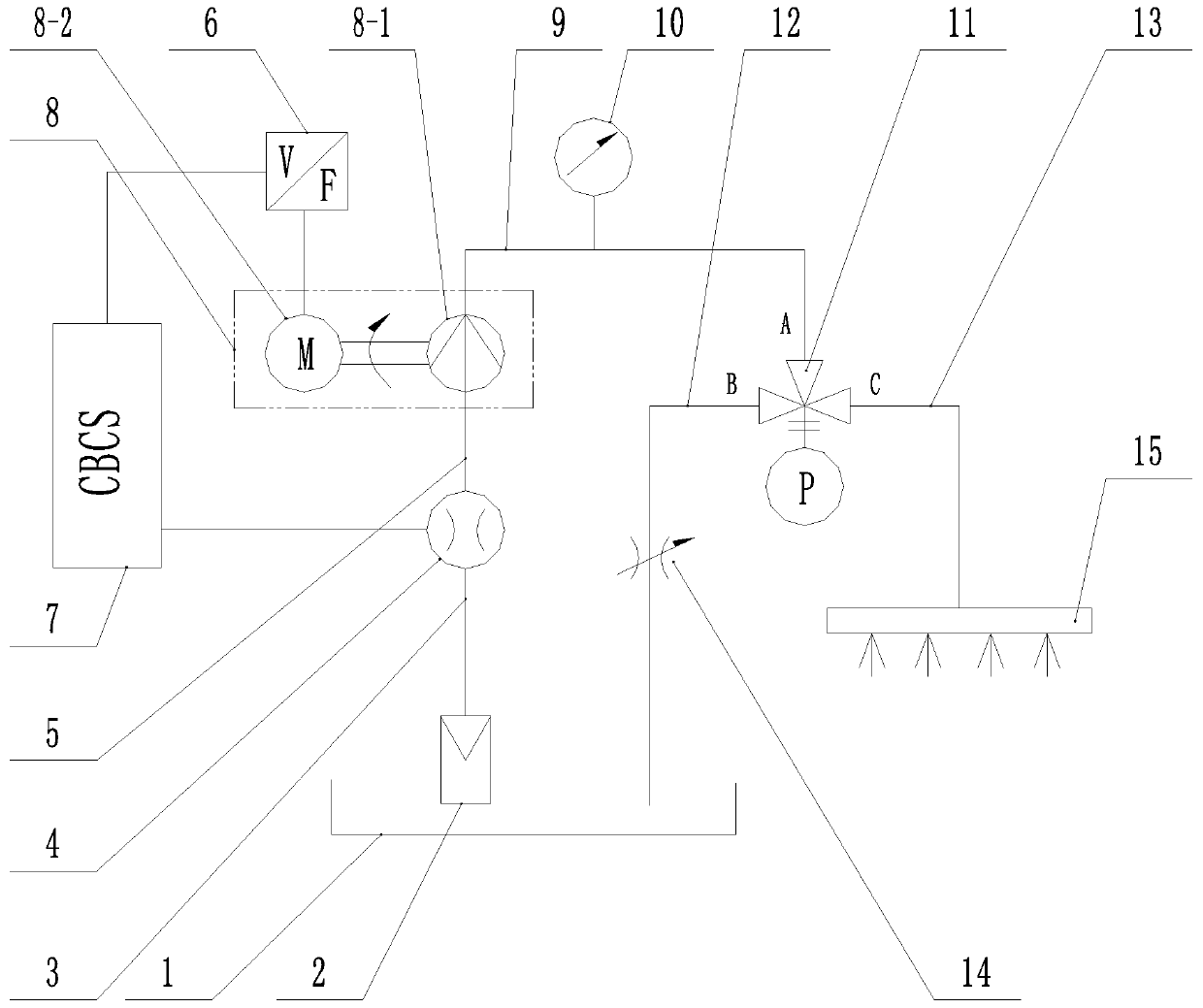
[0047] refer to figure 1 , is a structural schematic diagram of Embodiment 1 of the present invention, a plant-mixed metering water supply system, comprising
[0048] A water tank 1, the water tank 1 includes a water outlet and a water inlet;
[0049] water pump 8;
[0050] The first water suction pipe 3, one end of the first water suction pipe 3 communicates with the water outlet of the water tank 1, and the other end of the first water suction pipe 3 communicates with the water pump 8;
[0051] Electronic flow meter 4, electronic flow meter 4 is connected on the first water suction pipe 3;
[0052] A computer batching control system 7, one end of the computer batching control system 7 is connected to the electronic flowmeter 4 through an electrical signal line, and the other end of the computer batching control system 7 is connected to the water pump 8 through an electrical signal line;
[0053] The frequency converter 6, the other end of the computer batching control sys...
Embodiment 2
[0067] Compared with Embodiment 1, the difference of this embodiment is that: the water pump 8 is a centrifugal pump, and the water pump 8 includes a pump body 8-1 and a drive motor 8-2, and the drive motor 8-2 is connected to the pump body 8 -1, the drive motor 8-2 is connected to the other end of the frequency converter 6 through wires.
[0068] In actual use: the water pump 8 includes a pump body 8-1 and a drive motor 8-2, the drive motor 8-2 is connected to the pump body 8-1, and the other end of the frequency converter 6 is connected to the drive motor 8-2 of the water pump 8 through a wire. 2 connection, after the frequency converter 6 receives the signal, the motor speed of the driving motor 8-2 of the water pump 8 is controlled by the frequency conversion current to control the water output of the water pump 8, and the accuracy of the water output of the water pump 8 is controlled through this structure.
Embodiment 3
[0070] Compared with Embodiment 2, the difference of this embodiment is that the pump body 8-1 includes a water inlet and a water outlet, and the water inlet of the pump body 8-1 communicates with the other end of the first suction pipe 3 , The water outlet of the pump body 8-1 communicates with one end of the water outlet pipe 9.
[0071] During actual use: the water extracted during the work of the water pump 8 enters the water inlet of the pump body 8-1 through the first water suction pipe 3, and then enters the water outlet pipe 9 from the water outlet of the pump body 8-1.
PUM
 Abstract
Description
Claims
Application Information
 - R&D
- Intellectual Property
- Life Sciences
- Materials
- Tech Scout
- Unparalleled Data Quality
- Higher Quality Content
- 60% Fewer Hallucinations
Browse by: Latest US Patents, China's latest patents, Technical Efficacy Thesaurus, Application Domain, Technology Topic, Popular Technical Reports.
© 2025 PatSnap. All rights reserved.Legal|Privacy policy|Modern Slavery Act Transparency Statement|Sitemap|About US| Contact US: help@patsnap.com


