Transverse moving and feeding mechanism

A technology of traversing and decelerating motors, which is applied in the direction of conveyors, conveyor objects, rollers, etc., and can solve the problems of inflexible relative positions, inflexibility, waste, etc.

Pending Publication Date: 2020-04-10
SUZHOU KEBER PRECISION MACHINERY
View PDF0 Cites 1 Cited by
  • Summary
  • Abstract
  • Description
  • Claims
  • Application Information

AI Technical Summary

Problems solved by technology

[0002] When machining large-scale engineering plates, it is necessary to cooperate with the feeding mechanism to carry and transport the materials so that the plates can move in each station; due to the large volume of large-scale engineering plates, each station is mostly arranged in a line, and each station The relative position is not flexible enough and cannot be modified according to the customer site, resulting in a large footprint and waste; and the design of the traverse feeding mechanism perpendicular to the normal feeding direction can solve this problem; but because the normal feeding mechanism has two The side generally has a rib structure, and direct traversing will cause interference. Even if there is no rib, direct traversing will also rub against the material roller in the normal direction, so it is necessary to lift the plate to a certain height when traversing; and due to large The load of the plate is relatively large, and the general direct lifting mechanism is not competent, and there is a risk of failure of air and power failure

Method used


Image

  • Transverse moving and feeding mechanism
  • Transverse moving and feeding mechanism

Examples


Embodiment Construction

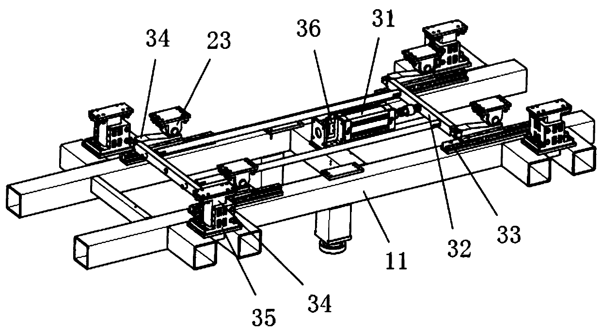
[0012] The present invention will be further described in detail below in conjunction with the accompanying drawings and specific embodiments.

[0013] Such as Figure 1-2 As shown, a traversing feeding mechanism according to the present invention includes a base 11, a traversing drive device, a lifting frame 22 and a lifting drive assembly; the lifting drive assembly includes a forward moving cylinder 31 and a forward connecting frame 32, The forward connecting frame 32 is made up of two connecting plates and two connecting rods, both ends of the two connecting plates are provided with lifting seats 34, and the base 11 is provided with four forward sliding rails 33 which cooperate with the lifting seats 34 , the forward cylinder 31 drives the lifting seat 34 to slide along the forward slide rail 33 through the forward connecting frame 32; the four corners of the bottom of the lifting frame 22 are provided with lifting rollers 23, and the lifting seat 34 is provided with lifti...


PUM


Abstract

The invention discloses a transverse moving and feeding mechanism which comprises a base, a transverse moving drive device, a lifting frame and a lifting drive assembly. The lifting drive assembly comprises a front moving air cylinder and a front moving connecting frame. A front moving sliding rail is arranged on the base. An elevating base is arranged on the front moving connecting frame. Liftingrolling wheels are arranged on the bottom of the lifting frame. The base is further provided with a lifting guide base. A lifting guide column is arranged on the bottom of the lifting frame. According to the scheme, the lifting structure of the lifting frame is designed on the base, the transverse moving roller on the lifting frame can drive plates to be jacked, the height of the plates is increased, and the situation that other surrounding mechanisms influence feeding of the plates is avoided. As the plates are heavy, lifting driving is changed from the vertical direction to the horizontal direction, load force of the air cylinder is converted into bearing force of the base, and the failure risk of gas and electricity cutting off is reduced. The transverse moving mechanism can be embedded into various material feeding mechanisms, the defect of one-direction feeding is changed, clients can make a choice flexibly according to the actual sites, and the site utilization rate is improved.

Description

technical field [0001] The invention relates to a traverse feeding mechanism. Background technique [0002] When machining large-scale engineering plates, it is necessary to cooperate with the feeding mechanism to carry and transport the materials so that the plates can move in each station; due to the large volume of large-scale engineering plates, each station is mostly arranged in a line, and each station The relative position is not flexible enough and cannot be modified according to the customer site, resulting in a large footprint and waste; and the design of the traverse feeding mechanism perpendicular to the normal feeding direction can solve this problem; but because the normal feeding mechanism has two The side generally has a rib structure, and direct traversing will cause interference. Even if there is no rib, direct traversing will also rub against the material roller in the normal direction, so it is necessary to lift the plate to a certain height when traversi...

Claims


Application Information

Patent Timeline
Patent Type & Authority Applications(China)
IPC IPC(8): B65G39/18B65G13/06
CPCB65G13/06B65G39/18B65G2201/022
Inventor 苏伟
Owner SUZHOU KEBER PRECISION MACHINERY
Why Eureka
Try Eureka