Power distribution support module used in direct-current charging pile

A DC charging pile and charging module technology, which is applied in charging stations, electric vehicle charging technology, electric vehicles, etc., can solve the problem that the charging module cannot be used, affects the charging voltage and charging current of the B charging gun, and battery safety hazards, etc. question

Pending Publication Date: 2020-04-10
深圳市飞优雀新能源科技有限公司
View PDF0 Cites 0 Cited by
  • Summary
  • Abstract
  • Description
  • Claims
  • Application Information

AI Technical Summary

Problems solved by technology

[0017] 1) Several power output contactors and power support contactors need to be used, resulting in a very large investment in components. Usually, the market price of such high-current contactors is more than 1,000 yuan each, and the volume is relatively large
[0018] 2) When multiple charging guns work at the same time, if the vehicle battery corresponding to a certain charging gun needs to be charged with a large flow rate, and the vehicle battery corresponding to the charging guns on both sides is charged at a low flow rate, at this time, the certain charging gun needs to be charged. The low-flow charging guns across both sides are charged by other charging modules that are in idle state. Since the charging modules are connected in parallel, this will inevitably lead to the charging guns that require low-flow charging will increase the charging flow, resulting in unnecessary Necessary waste of resources
[0020] 4) For the above point

Method used


Image

  • Power distribution support module used in direct-current charging pile
  • Power distribution support module used in direct-current charging pile
  • Power distribution support module used in direct-current charging pile

Examples


Embodiment Construction

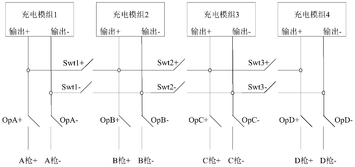
[0046] The power distribution support module (hereinafter referred to as the support module) used in the DC charging pile (hereinafter referred to as the charging pile) of the present invention is suitable for DC charging modules with an odd number, an even number of charging modules, and a combination of odd and even charging modules. charging pile, and each group of charging modules and any charging gun installed on the charging pile has a separate power supply switch branch circuit, when a certain group of charging modules is in an idle state (the charging gun is not charged ), it can supply power for any charging gun independently according to the command of the charging pile host computer, without any influence from other charging modules that are charging any charging gun.

[0047] Each charging module includes at least one charging module with standard output power, and the output power of each charging module is an integral multiple of 5kW, preferably each charging modu...


PUM


Abstract

The invention discloses a power distribution support module used in a direct-current charging pile. The power distribution support module can distribute any charging module in an idle state in the direct-current charging pile to any charging gun on the charging pile according to charging requirements. Each charging module is independently connected with a plurality of charging guns through a switching matrix circuit which comprises a plurality of groups of switch branch circuits and corresponds to the charging module. Each group of switch branch circuit consists of a positive path and a negative path, the input end and the output end of the positive path are respectively connected with the positive output end of the charging module and the positive input end of the corresponding charging gun, the input end and the output end of the negative path are connected with the negative output end of the corresponding charging gun and the negative input end of the charging module respectively, and connection or disconnection of each group of switch branch circuit is controlled by an upper computer of the charging pile. The equipment cost of the charging pile is reduced, the driving speed ishigh, the utilization rate of each charging module can be fully improved, the internal space of the direct-current charging pile is reduced, and the charging speed under power support application is increased.

Description

technical field [0001] The invention relates to an electric vehicle charging pile, in particular to a power distribution support module between a charging module in a DC charging pile and each charging gun. Background technique [0002] At present, the development of electric vehicle charging pile industry is in full swing. With the continuous improvement of BMS battery management system, the power requirements for charging piles are also getting higher and higher. [0003] At present, many high-power DC charging pile systems with multiple charging guns have appeared on the market. For these high-power charging piles with multiple guns, there are multiple unit charging modules inside (if the power of each unit charging module is 20kW, then the charging pile with 120kW has six unit charging modules), how to scientifically deploy It is an urgent problem to be solved that the charging modules of each unit in the pile provide reasonable power supply for multiple guns that enter...

Claims


Application Information

Patent Timeline
IPC IPC(8): B60L53/31B60L53/30B60L53/60
CPCB60L53/30B60L53/31B60L53/60Y02T10/70Y02T10/7072Y02T90/12
Inventor 黄书锐卢允初
Owner 深圳市飞优雀新能源科技有限公司
Why Eureka
Try Eureka