Traction device for house building rebars

A traction device and steel bar technology, applied in the field of construction, can solve problems such as inability to handle, rust falling off on the surface of steel bars, large resistance, etc., and achieve the effects of convenient and fast straightening, convenient adjustment and fixing, and prevention of extrusion

Active Publication Date: 2020-04-10
ZHONGXIN CONSTR GROUP
View PDF7 Cites 0 Cited by
  • Summary
  • Abstract
  • Description
  • Claims
  • Application Information

AI Technical Summary

Problems solved by technology

[0003] There are deficiencies in the currently used steel bar traction devices for building construction. When building high-rise buildings in areas with heavy humidity or rain, because more steel bars are needed, the disc-shaped steel bars are often stored, which will cause the steel bars to rust for a long time. , in the process of pulling and straightening the steel bar, the rust on the surface of the steel bar will fall off. It is prone to relatively large swings, which will endanger the workers near the traction device. On the one hand, the steel bar with a large curvature will have a large resistance to the reinforcement opening during the traction and straightening process, which is inconvenient for the reinforcement opening of the traction device. For protection, on the other hand, sometimes in order to prolong the construction period, in order to prevent the steel bar from rusting and enhance the service life of the steel bar, a layer of protective liquid will be coated on the surface of the steel bar. uneven, therefore, a traction device for building steel bars is proposed to address the above problems

Method used


Image

  • Traction device for house building rebars
  • Traction device for house building rebars
  • Traction device for house building rebars

Examples


Embodiment Construction

[0027] In order to make the technical means, creative features, goals and effects achieved by the present invention easy to understand, the present invention will be further described below in conjunction with specific embodiments.

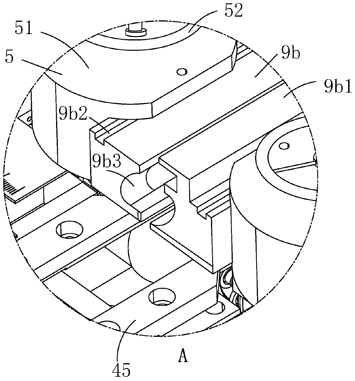
[0028] Such as Figure 1-Figure 9As shown, a traction device for building steel bars includes a frame 1, the interior of the frame 1 is installed with a distribution box 2 for internal wiring and switch installation, and the top of the frame 1 is installed with a useful The adjusting mechanism 4 for adjusting the spacing; the top of the adjusting mechanism 4 is equipped with a guiding mechanism 9b for steel bar guidance, and the fixing mechanism 5 is fixed between the guiding mechanism 9b and the adjusting mechanism 4; the shaft of the guiding mechanism 9b A liquid coating mechanism 6 for coating the steel bar surface is provided in the direction of the centerline, and one end of the liquid coating mechanism 6 is equipped with a frustum-shaped rei...


PUM

PropertyMeasurementUnit
angleaaaaaaaaaa

Abstract

The invention relates to the field of buildings, in particular to a traction device for house building rebars. The device comprises a frame, an adjusting mechanism for adjusting spacing, and a guide mechanism for guiding the rebars, and the guide mechanism and the adjusting mechanism are fixed through a fixing mechanism; the device further comprises a liquid coating mechanism used for liquid coating on the surfaces of rebars, one end of the liquid coating mechanism is provided with a rebar inlet, the top portion of the frame is provided with a traction mechanism, the internal portion of the traction mechanism communicates with the liquid coating mechanism, the frame is internally provided with a motor, the motor is connected with a speed reducer, the output shaft of the speed reducer is connected with the traction mechanism through a gear, and the frame is internally provided with a collection mechanism used for collecting steel bar scrap iron. The traction device for house building rebars can quickly pre-straighten rebars, can protect the rebar inlet, can collect the scrap iron at the surfaces of the rebars, can uniformly coat liquid on the surfaces of the rebars, and is high in working efficiency.

Description

technical field [0001] The invention relates to the construction field, in particular to the traction device for building steel bars. Background technique [0002] With the development of the construction industry and the improvement of people's living standards, people's requirements for building housing have also increased. Steel bars are an important building material, but in order to facilitate transportation, steel bars are often rolled into disks for transportation. After arriving at the construction site, it is necessary to pull and straighten the disc-shaped steel bars for use, which is convenient for workers to construct. Therefore, the steel bar pulling device is an indispensable tool for house construction. [0003] There are deficiencies in the currently used steel bar traction devices for building construction. When building high-rise buildings in areas with heavy humidity or rain, because more steel bars are needed, the disc-shaped steel bars are often stored, ...

Claims


Application Information

Patent Timeline
Patent Type & Authority Applications(China)
IPC IPC(8): B21F23/00B21F1/02B08B1/02B08B1/04B08B15/04B05C1/06B05C13/02B05C11/10
CPCB05C1/06B05C11/1039B05C13/02B08B1/002B08B1/02B08B1/04B08B15/04B21F1/02B21F23/00
Inventor 王桦陈苗龙奕锋王江娟韩银洁王宇炜
Owner ZHONGXIN CONSTR GROUP
Why Eureka
Try Eureka