Method for generating mirror image motion and mirror image motion device

A motion device and mirror technology, applied in passive exercise equipment, physical therapy and other directions, can solve the problems of low reliability, high cost, limb injury and other problems of the whole machine, and achieve the effect of good application prospect, low cost and simple structure

Active Publication Date: 2020-04-10
CIXI INST OF BIOMEDICAL ENG NINGBO INST OF MATERIALS TECH & ENG CHINESE ACAD OF SCI +1
View PDF7 Cites 4 Cited by
  • Summary
  • Abstract
  • Description
  • Claims
  • Application Information

AI Technical Summary

Problems solved by technology

The main problems of using this method to generate mirror motion are: multiple sensing elements, driving elements, control systems and power supplies are required, the system is complex, the cost is high, and the reliability of the whole machine is low due to the complexity of the system; in addition, The mechanical mechanism of this system is mostly a multi-degree-of-freedom mechanism, and there is coupling between each degree of freedom. In order to realize the coordinated control of the limbs on both sides, a complex control system is required to achieve the above tasks; at the same time, due to the introduction of active drive components, when When the control system fails or the drive components fail, the active components introduced in the entire man-machine system may cause a certain degree of damage to the user's limbs

Method used


Image

  • Method for generating mirror image motion and mirror image motion device
  • Method for generating mirror image motion and mirror image motion device
  • Method for generating mirror image motion and mirror image motion device

Examples


Embodiment 1

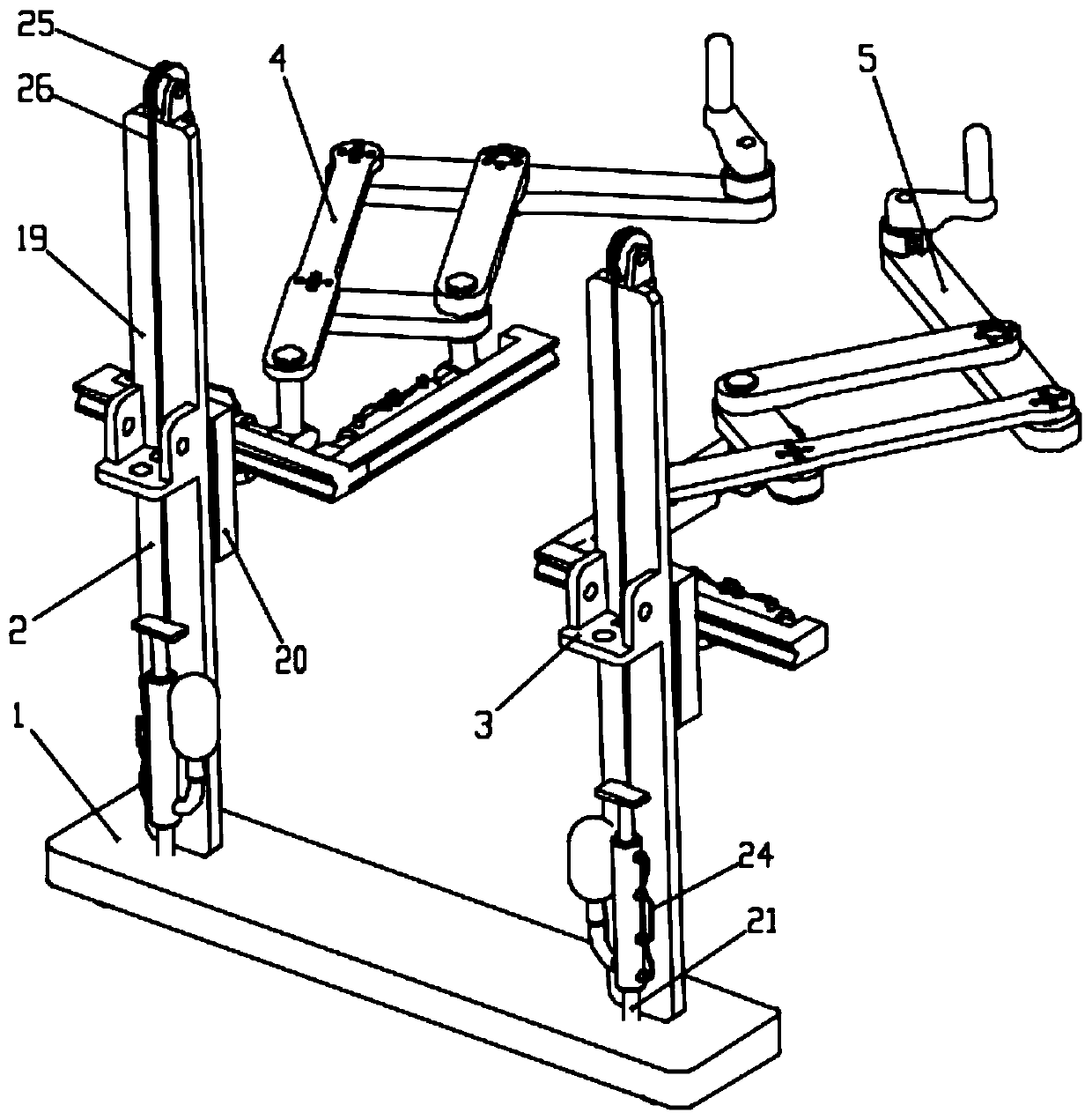
[0037] Mirror motion devices such as figure 2 As shown, it includes a base 1 , a first linear motion mechanism 2 , a second linear motion mechanism 3 , a first plane transmission mechanism 4 and a second plane transmission mechanism 5 . The structure of the first linear motion mechanism 2 is exactly the same as that of the second linear motion mechanism 3 . The structure of the first plane transmission mechanism 4 is exactly the same as that of the second plane transmission mechanism 5 .

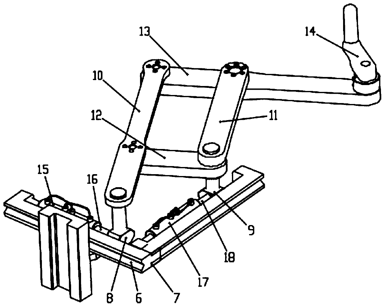
[0038] The first plane transmission mechanism 4 includes a guide rail along the X direction, called X guide rail 6, a guide rail 7 along the Y direction, called Y guide rail 7, an X slider 8 that can move along the X guide rail, and a Y guide rail that can move along the Y guide rail. The slider 9 and the four connecting rods are respectively the first connecting rod 10 , the second connecting rod 11 , the third connecting rod 12 and the fourth connecting rod 13 . Four connecting rods for...

Embodiment 2

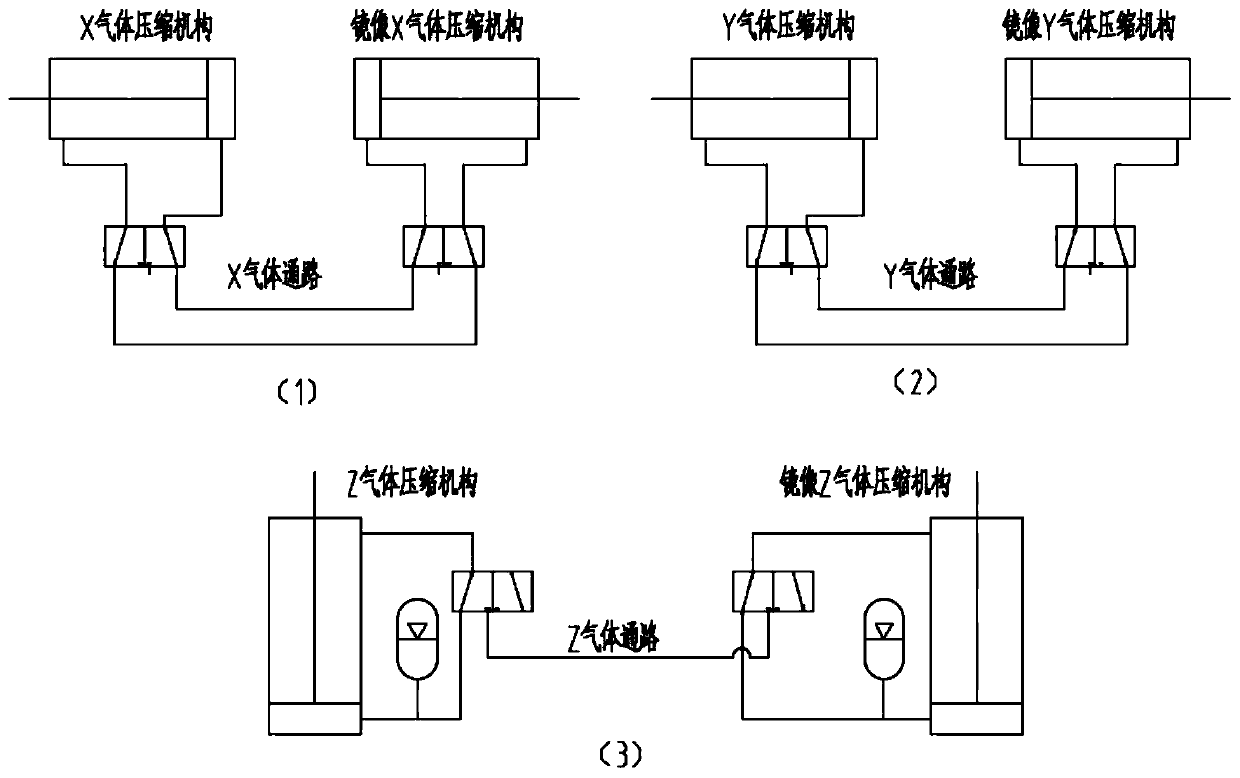
[0058] In this embodiment, the structure of the mirror motion device is basically the same as that in Embodiment 1, the difference is that a safety valve is set at the communication point of the gas passage of the X gas compression mechanism in the two plane transmission mechanisms, so as to realize the The movement of the mirror image can be limited or protected. Similarly, a safety valve is provided at the connection of the gas passage of the Y gas compression mechanism in the two planar transmission mechanisms; a safety valve is provided at the connection of the gas passage of the Z gas compression mechanism in the two linear motion mechanisms.

Embodiment 3

[0060] In this embodiment, the structure of the mirror motion device is basically the same as that in Embodiment 1, the difference is that the Z gas compression mechanism is set at one end of the compression spring, and the other end of the compression spring is connected to the base, and the spring force overcomes the linear motion mechanism. And the gravity of the plane transmission mechanism.


PUM


Abstract

The invention provides a method for generating mirror image motions and a mirror image motion device; a user makes an active motion on one side limb, a motion decomposition mechanism decomposes the motion into linear motions along an X axis, a Y axis and a Z axis; then, the motion is converted into piston reciprocating motions through a gas compression mechanism to compress gas; the gas is communicated with a mirror image gas compression mechanism through a gas passage to drive the piston to do the same reciprocating motions, so that linear motions along the X'-axis, the Y'-axis and the Z'-axis are generated, and the limb on the other side is driven to do mirror image motions after coupling. The mirror image motion device is of a pure mechanical structure, is low in cost and can be appliedto the fields of rehabilitation training and the like.

Description

technical field [0001] The invention belongs to the technical field of multi-degree-of-freedom motion, and in particular relates to a method for generating mirror image motion and a mirror image motion device. Background technique [0002] Mirror movement refers to the involuntary movement of the other limb almost simultaneously when one limb moves voluntarily. The mirror motion device can generate mirror motion and can be applied in many fields, for example, it has a very positive effect on the rehabilitation of stroke patients. Compared with the traditional unilateral exercise device, the mirror exercise device can train the patient's affected side according to the patient's healthy side information, making full use of the patient's self-assessment ability and his own force perception ability, and avoiding the need for unilateral exercise devices. The hidden danger of injury when training the patient's affected limb. [0003] The current existing method for generating mi...

Claims


Application Information

Patent Timeline
IPC IPC(8): A61H1/02
CPCA61H1/0274A61H2201/1261A61H2201/1238A61H2205/06
Inventor 伏荣真左国坤杨茗予施长城宋涛
Owner CIXI INST OF BIOMEDICAL ENG NINGBO INST OF MATERIALS TECH & ENG CHINESE ACAD OF SCI
Why Eureka
Try Eureka