Wire temperature rise experimental device and experimental method thereof

A kind of technology of experimental device and experimental method

Active Publication Date: 2020-04-07
CEEC JIANGSU ELECTRIC POWER DESIGN INST
View PDF3 Cites 0 Cited by
  • Summary
  • Abstract
  • Description
  • Claims
  • Application Information

AI Technical Summary

Problems solved by technology

At present, there are no test methods and platforms applicable to large cross-section conductors in China, and there is a lack of test verification for design results at wind speeds greater than design

Method used


Image

  • Wire temperature rise experimental device and experimental method thereof
  • Wire temperature rise experimental device and experimental method thereof
  • Wire temperature rise experimental device and experimental method thereof

Examples


Embodiment 1

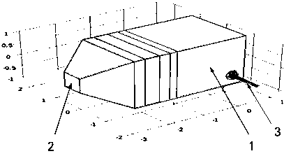
[0032] refer to figure 1 and figure 2 As shown, this embodiment is a wire temperature rise experimental device, including an experimental box 1, a fan unit 2, a wind speed measurement unit, a temperature measurement unit, a current source unit 5 and an acquisition control unit 4;

[0033] The two ends of the experimental box 1 are open, and the fan unit 2 is installed on the opening of one end of the experimental box 1, and the air outlet of the fan unit 2 faces the inner cavity of the experimental box 1; the start-stop and wind speed control input ends of the fan unit 2 are connected to the acquisition control unit 4;

[0034] The wind speed measurement unit includes a plurality of wind speed sensors that can be installed at the wire installation position in the inner cavity of the experiment box, and the output end of the wind speed sensor is connected to the acquisition control unit;

[0035] The temperature measurement unit includes a plurality of temperature sensors 6 ...

Embodiment 1-1

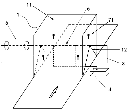
[0040] On the basis of Example 1, such as figure 2 As shown, in this embodiment:

[0041] The fan unit can also use independent fans and wind speed controllers, and the staff can directly operate the wind speed controllers to control the air volume of the fans. The air inlet of the fan (fan unit) is connected to the outside of the experimental box, and the air outlet faces the inner cavity of the experimental box. During wind speed control, the staff (or the collection control unit) can control the wind speed of the fan unit with a wind speed difference of 0.1m / s.

[0042] Wind speed component sensors 71 are respectively installed on a plurality of corresponding positions on the two side walls of the experimental box 1, such as figure 2 Among them, there are 2 groups of 4 wind speed component sensors; ambient temperature sensors are respectively installed on both sides of the experimental box 1; the output ends of the wind speed component sensors and the ambient temperatur...

Embodiment 2

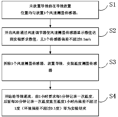
[0049] This embodiment is an experimental method using the wire temperature rise experimental device in embodiment 1-1, including:

[0050] S1, 3 wind speed measurement sensors are evenly arranged at the wire installation position where no wire is placed;

[0051] S2, turn on the fan unit to blow air to the inner cavity of the experiment box, collect the wind speed data sensed by the wind speed sensor, and adjust the speed of the fan unit according to the preset wind speed target value and real-time wind speed data until the wind speed data sensed by the wind speed sensor reaches the wind speed target value , and the deviation between multiple wind speed sensors does not exceed the preset deviation threshold; the preset deviation threshold is 0.1m / s, which can fluctuate slightly up and down;

[0052] S3, remove each wind speed sensor, install the wire to be tested with the temperature sensor attached to the wire installation position, and connect the current source unit and th...


PUM


Abstract

The invention discloses a wire temperature rise experimental device and an experimental method thereof. The experimental device comprises an experiment box, a fan unit, a wind speed measurement unit,a temperature measurement unit, a current source unit and an acquisition control unit. The two ends of the experiment box are opened, and a fan unit with an air outlet facing the inner cavity of the experiment box is arranged on the opening at one end of the experiment box; the wind speed measurement unit comprises a plurality of wind speed sensors which can be installed at wire installation positions in the inner cavity of the experiment box. The temperature measurement unit comprises a plurality of temperature sensors used for measuring the temperature of a measured wire, and the start-stopand wind speed control input end of the fan unit and the output ends of the wind speed sensors and the temperature sensors are connected with the acquisition control unit. Two side walls of the experiment box are provided with wire installation supports, and the current source unit comprises a current output end which is used for being connected with a tested wire, so as to form a current loop between the current source unit and the tested wire. When the experimental device provided by the invention is used for conducting a wire temperature rise experiment, the accuracy of a measurement resultcan be improved on the basis of ensuring convenient and fast measurement work.

Description

technical field [0001] The invention relates to the technical field of research on electrical properties of wires for power transmission and transformation, in particular to an experimental device for temperature rise of wires and an experimental method thereof. Background technique [0002] With the improvement of the transmission voltage level (AC 1000kV, DC ±1100kV), the method of increasing the transmission capacity by increasing the transmission voltage level has been applied to the extreme in the industry, and with the development of computing disciplines, scholars from various countries have re-studied the wire Thermal load capacity, by improving the calculation accuracy to determine the maximum allowable carrying capacity of the conductor, has important engineering value for tapping the potential transmission capacity of the existing power grid. At present, there is no test method and platform applicable to large cross-section conductors in China, and there is a lack...

Claims


Application Information

Patent Timeline
Patent Type & Authority Applications(China)
IPC IPC(8): G01R31/00
CPCG01R31/003
Inventor 姚成吴志明贾振宏彭伟奚海波袁飞郭瑞兴缪旭瑞陈剑王猛
Owner CEEC JIANGSU ELECTRIC POWER DESIGN INST
Why Eureka
Try Eureka