
Recoverable center type anchor cable and application method thereof

A technology for recovering cables and anchor cables, applied in excavation, sheet pile walls, construction, etc., can solve the problems of no resistance device, easy slippage, high cost, etc., and achieve the effect of convenient and fast recovery process and novel structural design

Pending Publication Date: 2020-04-07
姚炳祥
View PDF1 Cites 3 Cited by
  • Summary
  • Abstract
  • Description
  • Claims
  • Application Information

AI Technical Summary

Problems solved by technology

This method needs to provide enough pulling force to break the stop part integrated with the connecting body, and also need to overcome the clamping friction force between the connecting body and the stretching wire rope crimping clamp, so a larger pulling force is required. In addition, after loosening, the connecting body and the recovery cable are still clamped together by crimping clamps, and there is no resistance device that can separate the two; moreover, because the crimping clamps have no taper, the tensile member PC wire rope pulls It is difficult to clamp further when stretching, and it is easy to slip off
The scheme is complex in structure, high in cost and long in anchor head size

Method used


Image

  • Recoverable center type anchor cable and application method thereof
  • Recoverable center type anchor cable and application method thereof
  • Recoverable center type anchor cable and application method thereof

Examples


Embodiment Construction

[0038] The present application will be further described in detail below with reference to the accompanying drawings, and specific embodiments will be given.

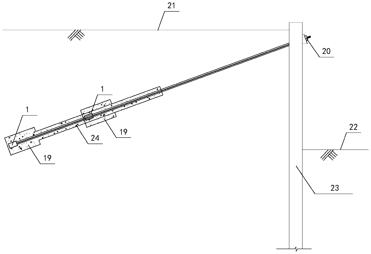
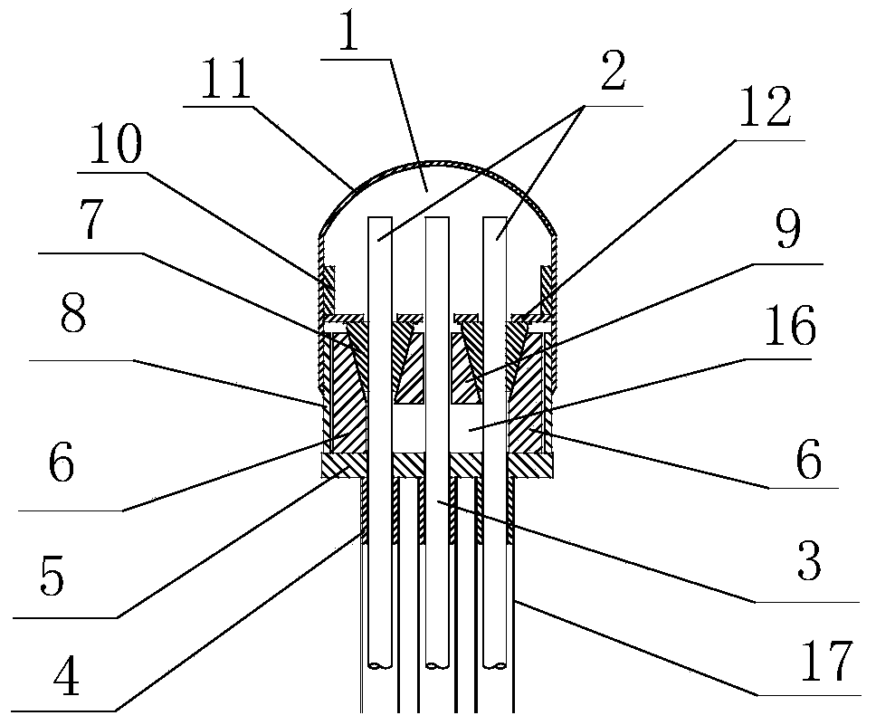
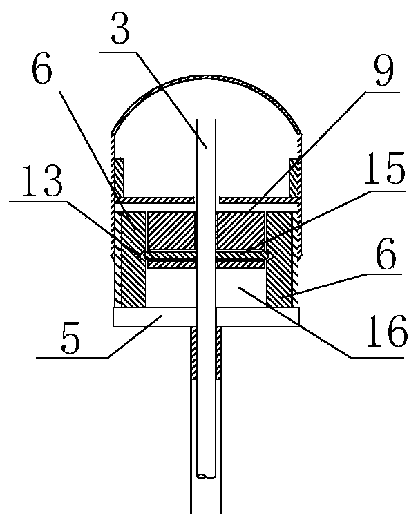
[0039] like figure 1 , figure 2 , image 3 Shown is a recyclable central anchor cable, which is composed of an anchor head 1, a working cable 2 and a recovery cable 3. The anchor head 1 includes an outer cover and a bearing plate 5. The bearing plate 5 is installed with a The anchor ring 6 is provided with a cavity inside the anchor ring 6, a central cylinder 9 is set on the upper part of the central part of the cavity, a reserved cavity 16 is set on the lower part, and the center of the central cylinder 9 is provided with a center for the recovery cable 3 to pass through. The recovery cable 3 passes through the carrier plate 5, and the end is located in the central hole.

[0040] like Figure 8 As shown, the space between the central cylinder 9 and the inner side wall of the anchor ring 6 is evenly combined into f...


PUM


Abstract

The invention relates to the field of buildings, in particular to a working cable recoverable center type anchor cable and an application method thereof. The anchor cable is composed of anchor heads,a working cable and a recovery cable. Each anchor head comprises a shell hood and a bearing plate, wherein an anchor ring is mounted on the bearing plate and is internally provided with a cavity; a center column body is arranged on the upper side of the cavity and is of a columnar integral structure; the lower side of the cavity is provided with a reserved cavity; a locking piece is arranged between the center column body and the inner sidewall of the anchor ring; the inner wall of the anchor ring is provided with a limiting groove; one end of the locking piece is located in the limiting groove to lock the center column body and the anchor ring, and the other end of the locking piece is maintained and fixed through the recovery cable in the radial position; as the recovery cable is pulledout, the locking piece can withdraw in the radial direction to cancel locking between the center column body and the anchor ring, and the center column body can move towards the reserved cavity to destroy tapered fixture accommodating spaces; and when clamping pieces lose clamping force, the working cable can be pulled out.

Description

technical field [0001] The present application relates to the field of construction, in particular to a recyclable central anchor cable for a working cable and a method for using the same. Background technique [0002] Since the early 1990s, my country has begun to use a large number of anchor cable support technology in the reinforcement of deep foundation pits and slopes of urban buildings. segment to provide greater pullout resistance. The length of the anchor cable is generally long, and the pull-out force is directly transmitted to the distal stable rock and soil layer through the steel strand and the anchor head. Due to the convenient construction and low cost of anchor cables, they are widely used in deep foundation pits of urban buildings. However, a large number of rod body materials such as steel bars and steel strands that are difficult to break are permanently buried in the ground, causing great difficulties to the foundation construction of the surrounding foll...

Claims


Application Information

Patent Timeline
Patent Type & Authority Applications(China)
IPC IPC(8): E02D5/74E02D17/04E02D17/20
CPCE02D5/74E02D17/04E02D17/20E02D17/202
Inventor 姚炳祥姚加奕
Owner 姚炳祥
Learn More