
A photoelectric deviation correcting instrument with adjustable use range

An adjustable and correcting device technology, applied in the field of photoelectric correcting device, can solve the problems of reducing the use effect of the device, increasing the workload, reducing the practicability of the device, etc., and achieving the effect of increasing the use effect and increasing the practicability.

Active Publication Date: 2022-05-03
深圳市晟睿通信有限公司
View PDF0 Cites 0 Cited by
  • Summary
  • Abstract
  • Description
  • Claims
  • Application Information

AI Technical Summary

Problems solved by technology

[0003] The existing photoelectric correction device adjusts the offset of the detection part through the adjustment device, and uses the upper and lower pressure rollers to press and fix the detection part, and moves the position of the pressure roller to adjust the position of the detection part, but the existing photoelectric correction device The position between the upper and lower pressure rollers is relatively fixed, so that the device can detect coils with a single thickness, but cannot meet the detection of coils with different thicknesses, reducing the practicability of the device
[0004] The photoelectric detection device sets the coiled material on the conveying roller. When in use, the conveying roller drives the coiled material to rotate for coil feeding. The length of the coiled material on the conveying roller of the existing photoelectric detecting device is single and fixed. When the length of the coiled material is relatively Hours, the coil will slide relative to the conveying roller during the rotation process, which increases the correction amount of the device, increases the workload, and reduces the practicability of the device
[0005] When the photoelectric detection device detects the lines on the detection piece, when the detection piece deviates, the position of the detection piece can be adjusted by moving the upper and lower pressure rollers, but when the detection piece is stretched and deformed, the detection device detects the line The position of the test piece remains unchanged, the device cannot judge that the state of the test piece is abnormal, the correction device does not adjust the test piece, and the test piece is in a stretched state, which may lose its original function and reduce the use effect of the device

Method used


Image

  • A photoelectric deviation correcting instrument with adjustable use range
  • A photoelectric deviation correcting instrument with adjustable use range
  • A photoelectric deviation correcting instrument with adjustable use range

Examples


Embodiment Construction

[0028] The following will clearly and completely describe the technical solutions in the embodiments of the present invention with reference to the accompanying drawings in the embodiments of the present invention. Obviously, the described embodiments are only some, not all, embodiments of the present invention. Based on the embodiments of the present invention, all other embodiments obtained by persons of ordinary skill in the art without making creative efforts belong to the protection scope of the present invention.

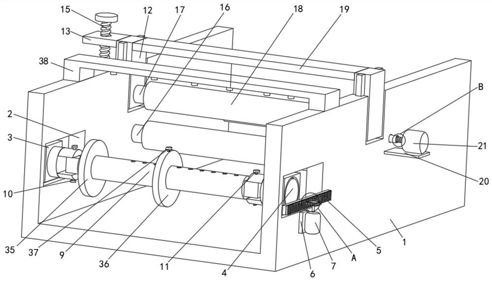
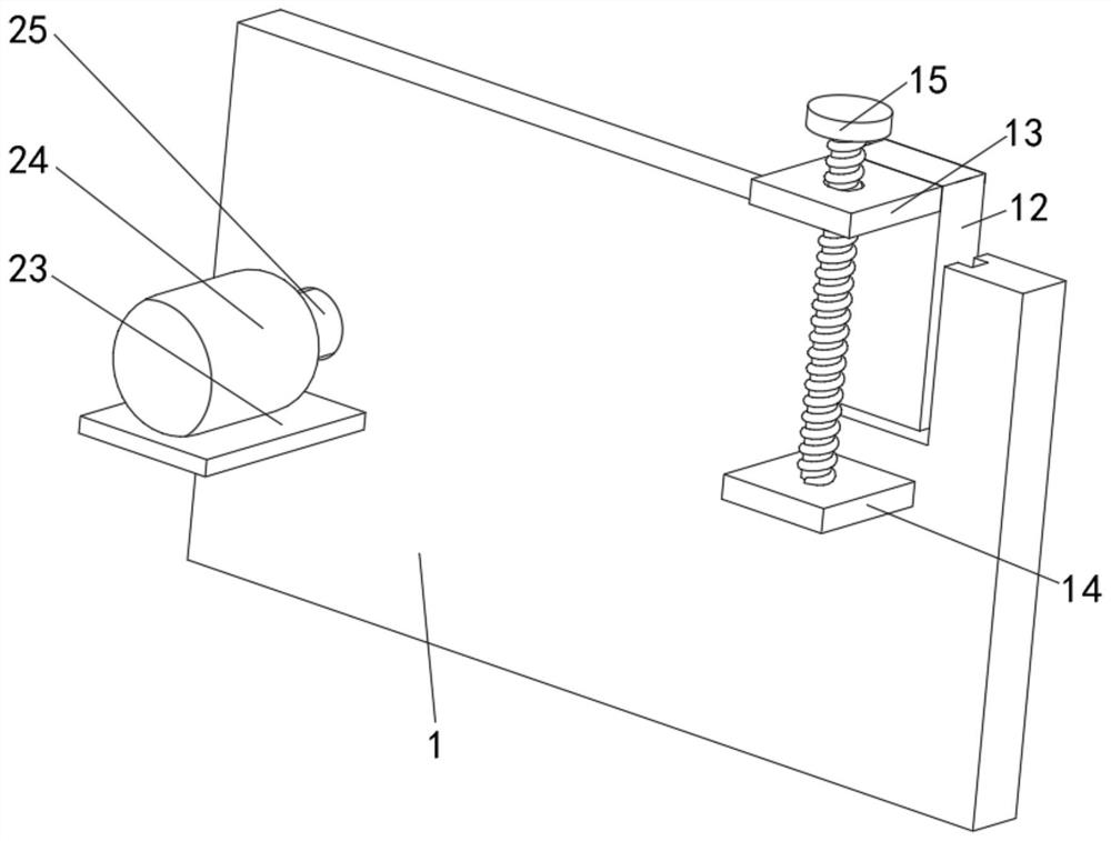
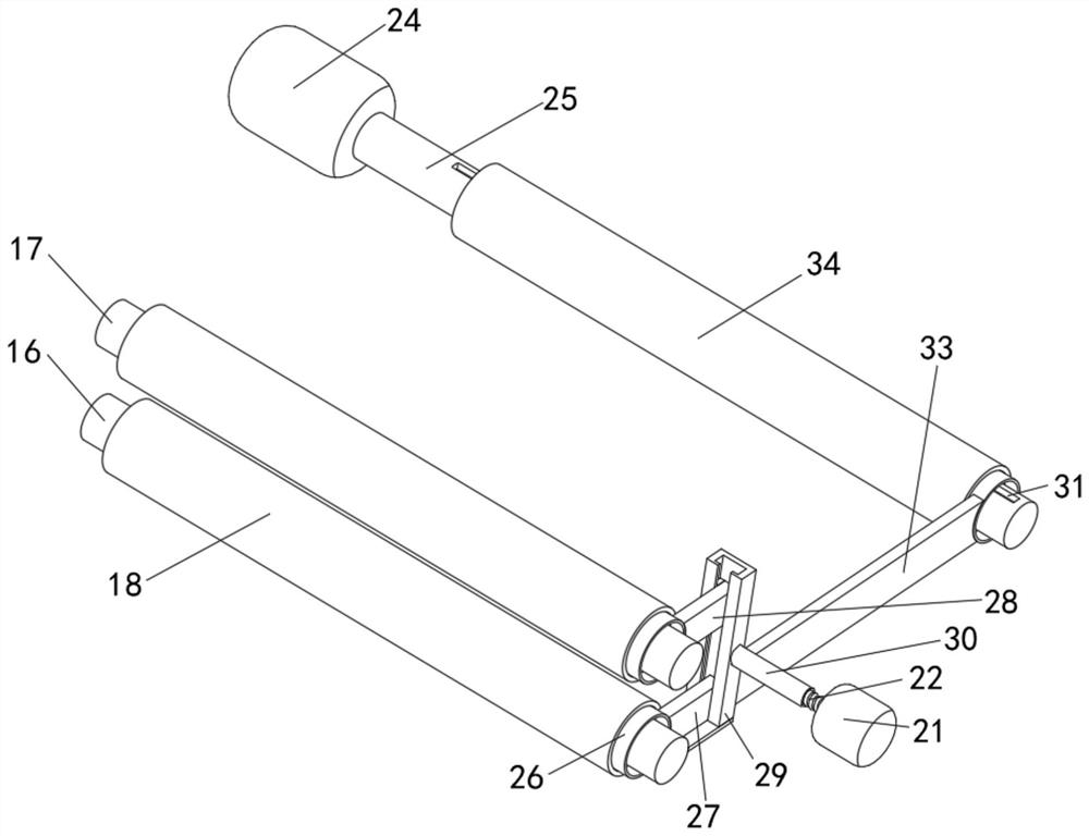
[0029] see Figure 1-8, a photoelectric correction device with an adjustable use range, including a housing 1, the left and right sides of the housing 1 are provided with chute 2, two moving blocks 3 are movably connected to the inner cavity of the chute 2, and the moving block 3 can be in the Sliding in the chute 2, the moving block 3 drives the conveying roller 9 to move back and forth through the splint 4, and fine-tunes the testing piece in the stretched s...


PUM


Abstract

The invention relates to the technical field of photoelectric deviation correction detection, and discloses a photoelectric deviation correction instrument with an adjustable use range, which includes a casing, and moving blocks are movably connected to the left and right sides of the casing, and the middle parts of the two moving blocks are A splint is movably connected, and a rack on the right side of the housing is fixedly installed on the right side of the splint. The right side of the housing is fixedly installed with a frame one, and the right side of the frame one is fixed. A motor is installed. The present invention meshes with the engaging plate through the threaded rod two, so that the engaging plate can move up and down, the engaging plate drives the lifting plate to move up and down, and the upper pressure roller installed on the right side of the lifting plate can move up and down following the lifting plate, thereby realizing Change the distance between the lower pressure roller and the upper pressure roller, and drive the upper pressure roller to move by turning the threaded rod 2, so that the upper pressure roller can press the detection piece, so that the device can detect coils of different thicknesses, increasing the practicality of the device sex.

Description

technical field [0001] The invention relates to the technical field of photoelectric deviation correction detection, in particular to a photoelectric deviation correction instrument with an adjustable use range. Background technique [0002] With the rapid development of basic processing fields such as chemical industry, papermaking, textile and clothing, packaging and printing, ferrous and non-ferrous metals, the development of automation control systems tends to be high-precision, high-resolution, high-adaptability, strip In the winding production process, various external disturbances often affect it, causing it to deviate during the walking process. The photoelectric correction device detects the line on the detection part through the detection device to judge the position of the detection part. Check whether the deviation occurs, and correct the deviation phenomenon of the strip during winding. [0003] The existing photoelectric correction device adjusts the offset of...

Claims


Application Information

Patent Timeline
Patent Type & Authority Patents(China)
IPC IPC(8): B65H23/02B65H20/02
CPCB65H23/0204B65H20/02B65H2701/1133
Inventor 吴祥仁蔡华珠
Owner 深圳市晟睿通信有限公司
Learn More