
Discharging device for injection molding machine

An injection molding machine and blanking technology, which is applied in the field of blanking devices for injection molding machines, can solve the problems of reducing the working efficiency of injection molding machines, increasing the working intensity of operators, and not setting up blanking devices, so as to avoid movement, increase productivity, and The effect of reducing downtime

Active Publication Date: 2020-04-07
利辛县美纶纺织有限责任公司
View PDF7 Cites 2 Cited by
  • Summary
  • Abstract
  • Description
  • Claims
  • Application Information

AI Technical Summary

Problems solved by technology

[0002] In the manufacture of plastic products, injection molding machines are usually used, and the plastic products need to be unloaded after the injection molding machine manufactures the plastic products, but the current injection molding machines do not have a blanking device, and the plastic products are usually stored in a collection box Afterwards, it is transported to the next process. During the collection process, only one collection box can be used at a time. When a collection box is full, the injection molding machine needs to be stopped and the collection box needs to be replaced, which reduces the operating efficiency of the injection molding machine and increases Increased the operating intensity of the operator, so it needs to be improved

Method used


Image

  • Discharging device for injection molding machine
  • Discharging device for injection molding machine

Examples


Embodiment Construction

[0019] In order to make the object, technical solution and advantages of the present invention clearer, the present invention will be further described in detail below in conjunction with the accompanying drawings and embodiments. It should be understood that the specific embodiments described here are only used to explain the present invention, not to limit the present invention. Based on the embodiments of the present invention, all other embodiments obtained by persons of ordinary skill in the art without creative efforts fall within the protection scope of the present invention.

[0020] In the description of the present invention, it should be noted that terms such as "first", "second" and "third" are only used to distinguish descriptions, and should not be understood as indicating or implying relative importance.

[0021] The orientation or positional relationship indicated by the terms "upper", "lower", "left", "right", "front", "rear", "inner", "outer", etc. is based o...


PUM


Abstract

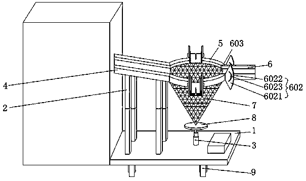
The invention discloses a discharging device for an injection molding machine. The discharging device comprises an installation bottom plate; a telescopic supporting rod and a hydraulic telescopic rodare fixedly installed on the installation bottom plate; and a material receiving groove body is fixedly installed at the top of the supporting rod. A plurality of movable material guiding mechanismsare arranged on a limiting sleeve; the lower end part of the limiting sleeve is fixedly connected with a material containing net bag; and therefore, in the use process of the discharging device, a product sliding out of the discharging opening of the injection molding machine can be guided into the material containing net bag through the material receiving groove body, and the overflow of the product caused by a condition that the flow guide speed of the movable material guide mechanisms is lower than the discharging speed of the discharge opening when the discharging speed of the injection molding machine is high can be avoided. After the processed product of the injection molding machine is guided into the material containing net bag, the processed product can be temporarily contained inthe material containing net bag when a collecting box is full and needs to be replaced; and therefore, shutdown under the situation that the collecting box is full and needs to be replaced is avoided, the shutdown frequency of the injection molding machine is reduced, productivity is greatly improved, and manufacturing cost is reduced.

Description

technical field [0001] The invention relates to the technical field of injection molding machines, in particular to a feeding device for injection molding machines. Background technique [0002] In the manufacture of plastic products, injection molding machines are usually used, and because the plastic products need to be blanked after the injection molding machine manufactures plastic products, the current injection molding machine does not have a blanking device, and the plastic products are usually stored in a collection box Afterwards, it is transported to the next process. During the collection process, only one collection box can be used at a time. When a collection box is full, the injection molding machine needs to be stopped and the collection box needs to be replaced, which reduces the operating efficiency of the injection molding machine and increases The operating intensity of the operator is increased, so it needs to be improved. Contents of the invention [...

Claims


Application Information

Patent Timeline
Patent Type & Authority Applications(China)
IPC IPC(8): B29C45/17
CPCB29C45/1769
Inventor 马金旭
Owner 利辛县美纶纺织有限责任公司
Learn More