Microscopic light path laser coupling repeated positioning device

A repetitive positioning and laser technology, applied in microscopes, optics, optical components, etc., can solve problems such as high cost and inability to achieve, and achieve the effect of reducing design and processing costs

Pending Publication Date: 2020-04-03
ZOLIX INSTR
View PDF0 Cites 5 Cited by
  • Summary
  • Abstract
  • Description
  • Claims
  • Application Information

AI Technical Summary

Problems solved by technology

[0005] The disadvantage of using the turntable to switch the optical filter to switch the laser light path is that if the design of the turntable is finalized, the number of filter components installed on the turntable will also be determined. Therefore, the number of laser light paths that can be coupled is also determined. It is determined that if it is necessary to expand and increase the laser light path in the future, it will not be possible
In addition, the technical solution of using the turntable requires the use of a high-precision turntable, and its cost is relatively high

Method used


Image

  • Microscopic light path laser coupling repeated positioning device
  • Microscopic light path laser coupling repeated positioning device
  • Microscopic light path laser coupling repeated positioning device

Examples


Embodiment Construction

[0032] It should be noted that, in the case of no conflict, the embodiments in the present application and the features in the embodiments can be combined with each other. The present invention will be described in detail below with reference to the accompanying drawings and examples.

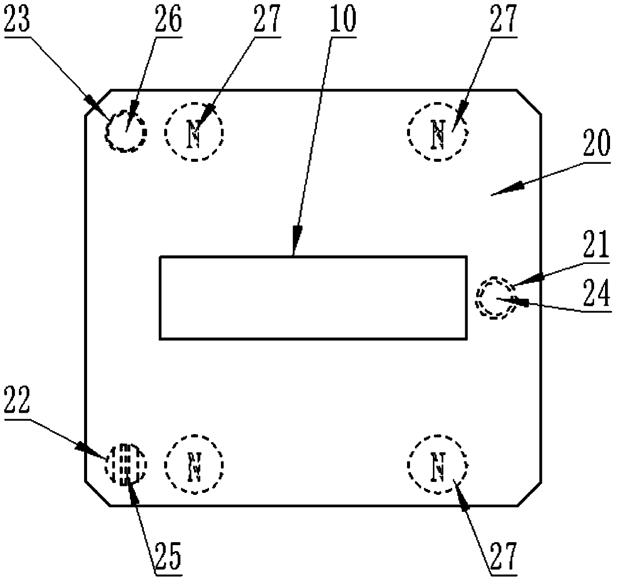
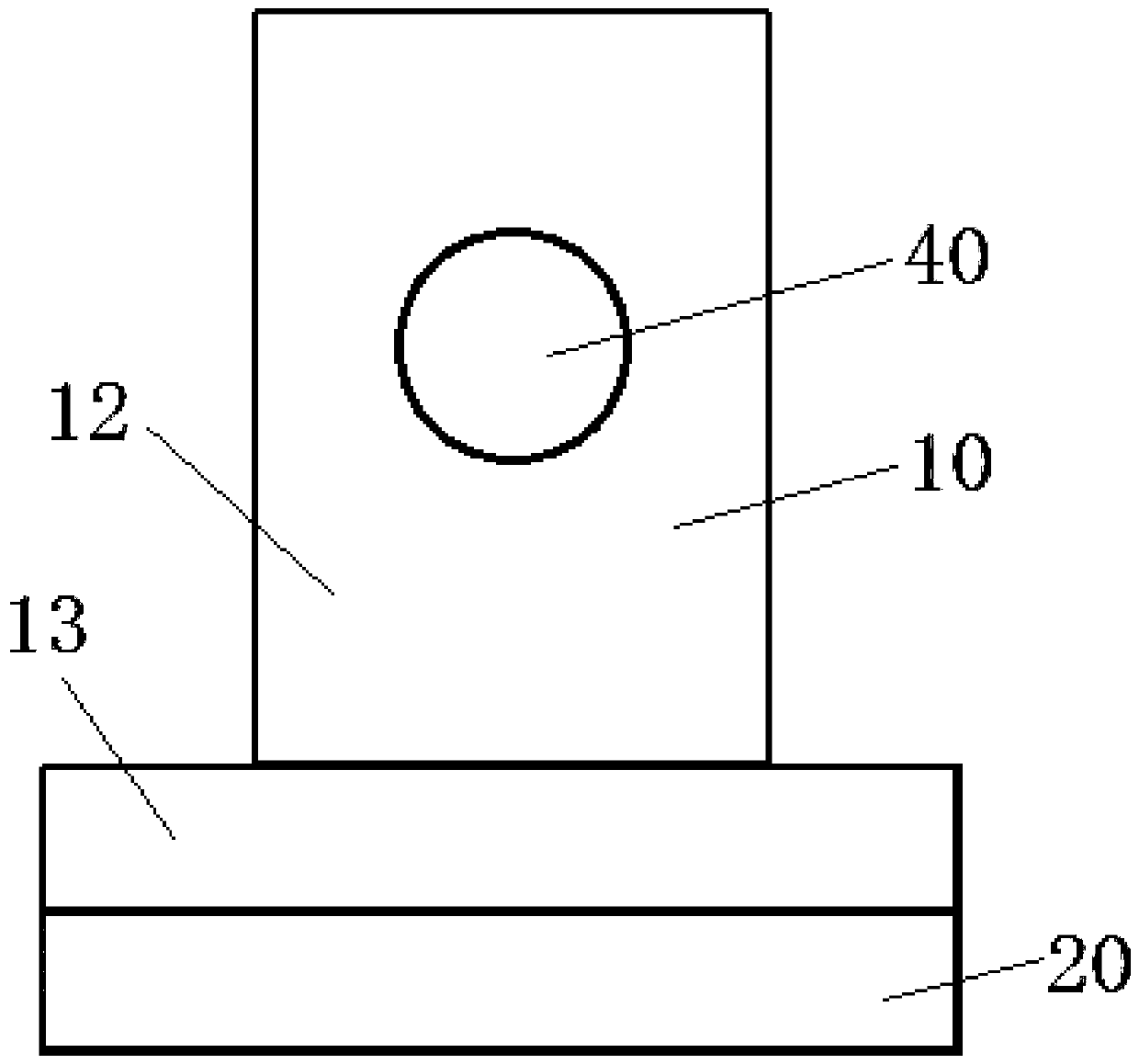
[0033] A microscopic optical path laser coupling repeat positioning device, comprising an upper lens frame 10 and a base 20 arranged up and down, three balls 30 are arranged between the upper lens frame 10 and the base 20, and three upper grooves are arranged in the upper surface of the base 20. The three upper grooves are distributed in a triangle, that is, the three upper grooves are not on the same straight line, and the three upper grooves are respectively the first upper groove 21, the second upper groove 22 and the third upper groove. Groove 23, the bottom surface of the first upper groove 21 is a tapered surface, the bottom surface of the second upper groove 22 is a V-shaped surface, the...


PUM


Abstract

The invention discloses a microscopic light path laser coupling repeated positioning device. The device comprise an upper glasses frame (10) and a base (20) which are arranged up and down, three balls(30) are arranged between the upper mirror bracket (10) and the base (20); three upper grooves are formed in the upper surface of the base (20); the three upper grooves are distributed in a triangular shape; the bottom surface of the first upper groove (21) is a conical surface; the bottom face of the second upper groove (22) is a V-shaped face, the bottom face of the third upper groove (23) is aplane, three lower grooves are formed in the lower surface of the upper mirror frame (10), the upper portions of the balls (30) are located in the lower grooves, the lower portions of the balls (30)are located in the upper grooves, and the centers of the three balls (30) are located in the same reference plane. The microscopic light path laser coupling repeated positioning device not only can realize high-repeatability microscopic light path laser coupling, but also can facilitate subsequent expansion and increase of a laser light path.

Description

technical field [0001] The invention relates to the field of optical equipment, in particular to a microscopic optical path laser coupling repeat positioning device. Background technique [0002] In micro-laser test equipment, such as micro-Raman, micro-fluorescence and other test systems, multiple lasers need to be configured, and different optical filters are required to couple the laser light path to the micro-light path, such as figure 1 As shown, it contains a detector 1, a laser 2, a microscopic illumination 3, a sample 4, a microscope 5, a camera 6, a laser coupling filter 7, a spectrometer coupling optical path 8 and a spectrometer 9. [0003] When switching the laser, it is necessary to switch the corresponding optical filter. If the installation and repeat positioning accuracy of the optical filter is not good, it will seriously affect the laser light path in the microscopic light path. In severe cases, the laser will not be able to pass through the microscope. Th...

Claims


Application Information

Patent Timeline
Patent Type & Authority Applications(China)
IPC IPC(8): G02B21/24G02B21/06G02B21/00
CPCG02B21/0004G02B21/06G02B21/24
Inventor 蔡宏太陈海霞
Owner ZOLIX INSTR
Why Eureka
Try Eureka