
Air-tight sealing device of head of belt conveyor

A belt conveyor and hermetic sealing technology, which is applied in the direction of engine sealing, mechanical equipment, engine components, etc., can solve the problem of affecting the working performance and service life of the device, improving the difficulty of equipment cleaning and maintenance costs, and the adverse effects of the working environment of the belt conveyor, etc. problems, to achieve the effect of improving the quality of equipment connection, reducing downtime for maintenance, and reducing the difficulty of cleaning

Pending Publication Date: 2020-04-03
JIANGSU JIANGDA MACHINERY
View PDF0 Cites 0 Cited by
  • Summary
  • Abstract
  • Description
  • Claims
  • Application Information

AI Technical Summary

Problems solved by technology

However, during the operation, the dust inside the equipment will overflow from the connection gap between the head shaft and the equipment shell, which will have a negative impact on the working environment quality of the belt conveyor.
At the same time, the spilled dust will partially stick to the connection gap, affecting the working performance and service life of the device, and has a negative impact on the quality of material transportation. The dust in the gap needs to be cleaned by disassembling the structure, which improves the equipment. Difficulty of cleaning and maintenance costs

Method used

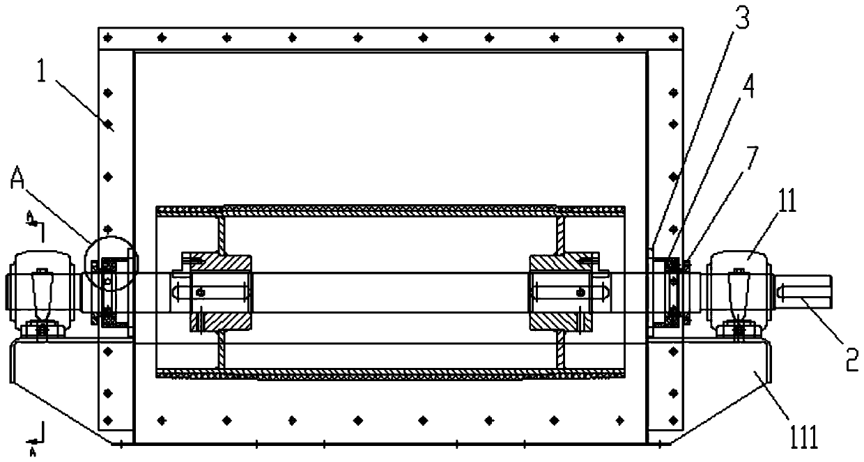

Image

  • Air-tight sealing device of head of belt conveyor
  • Air-tight sealing device of head of belt conveyor
  • Air-tight sealing device of head of belt conveyor

Examples


Embodiment Construction

[0018] The present invention will be further described below in conjunction with the accompanying drawings and specific embodiments.

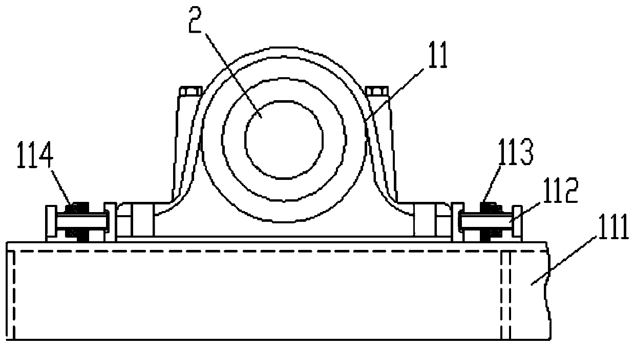
[0019] The structure of the head of the belt conveyor with the sealing device is as follows: figure 1 and 4 as shown, figure 2 and image 3 In order to highlight the structural features, some lines have been deleted. The two ends of the shaft 2 in the head housing 1 pass through the through hole of the housing and the sealing device in sequence, and are connected and positioned with the bearing seats 11 installed on both sides of the head housing 1. One end of the shaft 2 Used for connection with drive motors for rotary drive.

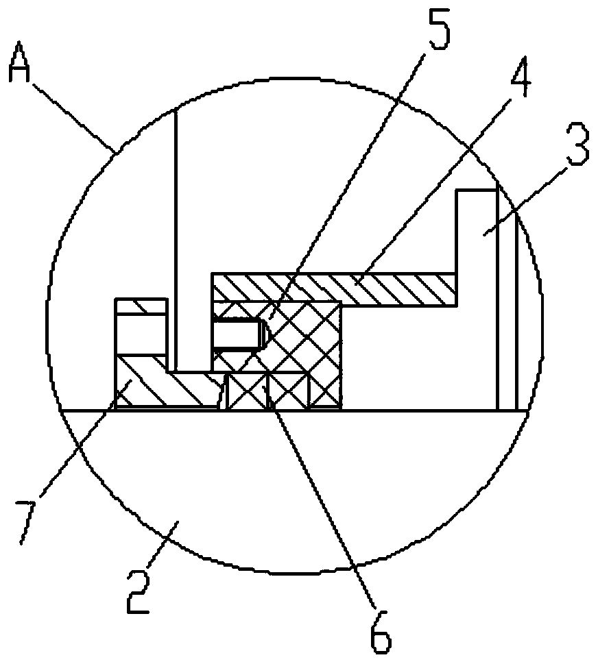
[0020] The structure of the sealing device is as follows figure 2 The figure includes a fixed plate 3 , a sealing plate 4 , a sealing gasket 5 and a sealing cover 7 arranged in sequence. The fixing plate 3 , the sealing tube 4 , the sealing gasket 5 and the sealing cover 7 are sequentially pierced to form an ins...


PUM


Abstract

The invention discloses an air-tight sealing device of a head of a belt conveyor applied to the field of belt conveying. The device structurally comprises a fixing plate, a sealing pipe, a sealing gasket and a sealing cover, wherein the fixing plate, the sealing pipe, the sealing gasket and the sealing cover are sequentially arranged; the end face of one end of the sealing pipe is coaxially weldedto the side face of the fixing plate, the sealing gasket is sleeved with the other end of the sealing pipe, the outer surface of the sealing gasket and the inner surface of the sealing pipe are welded and positioned, the inner surface of the sealing gasket is provided with an inner ring groove facing the sealing cover, one end of the sealing cover is internally sleeved with the inner ring groove,the space among the sealing cover, the sealing gasket and a shaft is filled with sealing filler in the inner ring groove, a gas ring cavity is defined by the fixing plate, the sealing pipe, the sealing gasket, the sealing filler and the shaft, and one side of the sealing pipe is provided with an air inlet. According to the device, dust is prevented from passing through the connecting gap betweenthe shaft and the shell through the gas pressure, so that the sealing operation to the connecting gap is realized, the auxiliary circumferential positioning for the shaft can be realized through the flow of circumferential air pressure, the equipment connecting quality is further improved, the connecting relative friction force is reduced, and the matched driving effect is improved.

Description

technical field [0001] The invention relates to a belt conveyor head air sealing device used in the field of belt conveyor material conveyance. Background technique [0002] Belt conveyors transport workpieces for important materials, especially large complete sets of equipment. During the application process, the end of the shaft of the head of the belt conveyor needs to be positioned and extended out of the corresponding head shell, and then the end positioning operation is realized by using the bearing seats on both sides of the head shell, and one end is connected with the drive The device is connected to realize the stable operation of the rotary drive. However, during the operation, the dust inside the equipment will overflow from the connection gap between the head shaft and the equipment casing, which will have a negative impact on the quality of the working environment of the belt conveyor. At the same time, the spilled dust will partially stick to the connection ...

Claims


Application Information

Patent Timeline
IPC IPC(8): F16J15/20F16J15/40
CPCF16J15/20F16J15/40
Inventor 倪新跃
Owner JIANGSU JIANGDA MACHINERY
Learn More