LED underground lamp with adjustable irradiation angle

A technology of LED buried lights and irradiation angles, which is applied to lighting devices, fixed lighting devices, lighting and heating equipment, etc., and can solve problems such as difficulty in adjusting the irradiation angle of buried lights

Active Publication Date: 2020-03-31
SHENZHEN TIAN YU HARDWARE & ELECTRICAL
View PDF10 Cites 5 Cited by
  • Summary
  • Abstract
  • Description
  • Claims
  • Application Information

AI Technical Summary

Problems solved by technology

[0005] The purpose of the present invention is to solve the problem that the irradiation angle of the buried light is difficult to adjust, and to provide an adjustable irradiation angle LED buried light which is convenient for adjusting the irradiation angle of the buried light

Method used


Image

  • LED underground lamp with adjustable irradiation angle
  • LED underground lamp with adjustable irradiation angle
  • LED underground lamp with adjustable irradiation angle

Examples


Embodiment 1

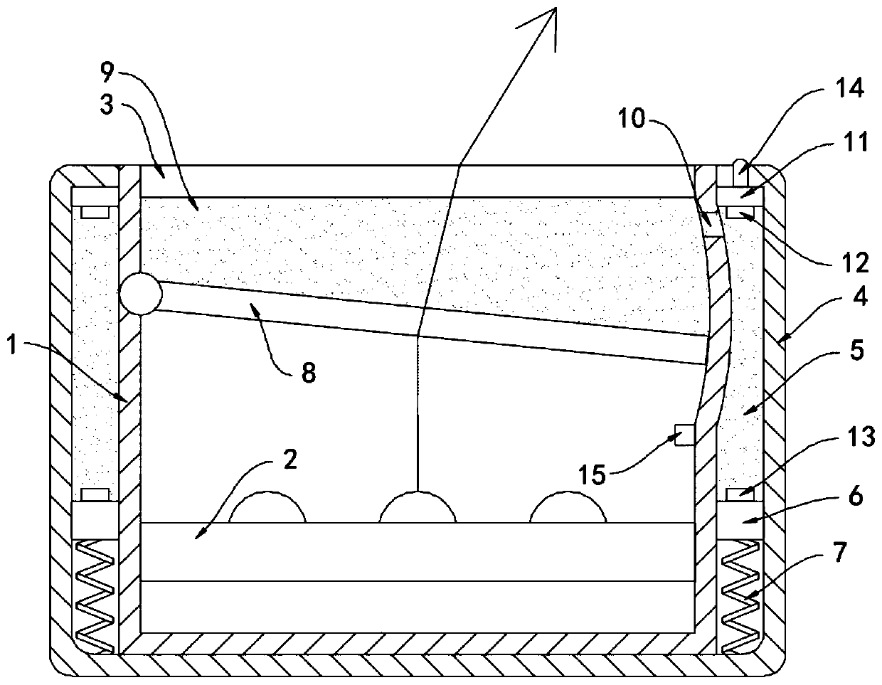
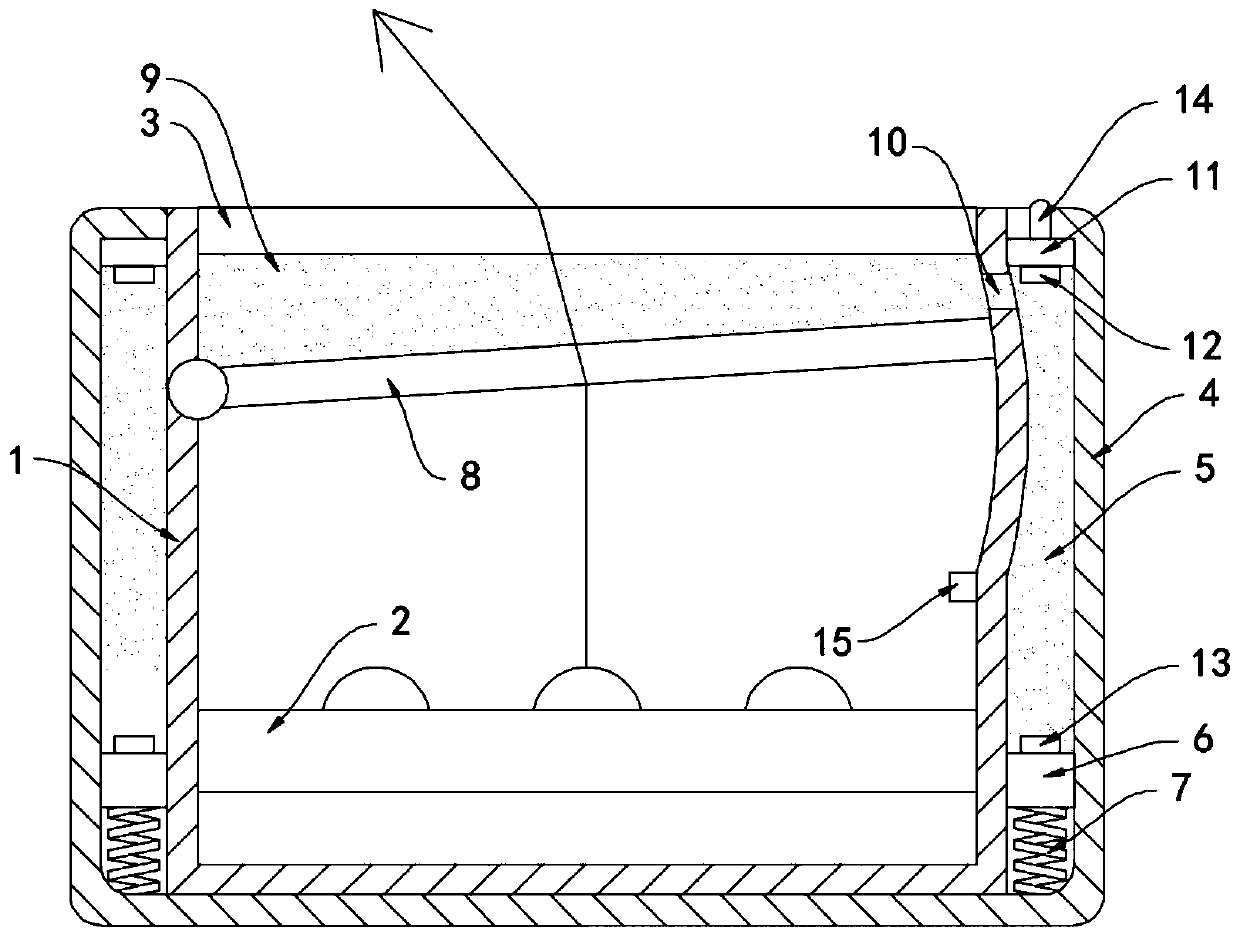
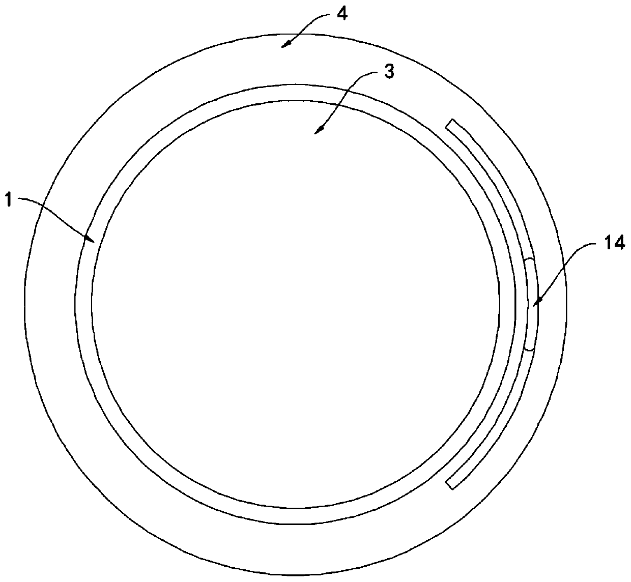
[0020] Such as Figure 1-4 As shown, an LED underground lamp with adjustable irradiation angle includes an inner casing 1 and an LED lamp group 2 installed in the inner casing 1. A transparent cover plate 3 is fixedly installed on the upper end of the inner casing 1. The inner casing 1. The outer casing 4 is fixedly connected with the outer casing. An annular cooling chamber 5 is formed between the inner casing 1 and the outer casing 4. The side wall of the annular cooling chamber 5 is sealed and slidably connected with a sealing ring 6. The sealing ring 6 is connected with the supporting spring 7 through the The bottom surface of the outer shell 4 is fixedly connected, and the inner side wall of the inner shell 1 is connected with a refraction plate 8 through hinge rotation, and the side wall at the other end of the refraction plate 8 is in sealing and sliding connection with the inner side wall of the inner shell 1. A limit block 15 is provided on the side wall, and the limi...

Embodiment 2

[0025] Such as Figure 5 As shown, the difference between this embodiment and Embodiment 1 is that a plurality of transparent air pockets 16 are evenly distributed in the refraction liquid, and the transparent air pockets 16 are filled with evaporating liquid, which can be dichloromethane, which is colorless and has a boiling point of The temperature is 39.5°C, the transparent airbag 16 is arranged in a spherical shape, and the transparent airbag 16 is made of deformable material.

[0026] In this embodiment, the LED lamp group 2 generates a lot of heat when it is working, and the temperature is transmitted to the transparent air bag 16 through the refraction liquid, which can cause the transparent air bag 16 to expand slightly, because the temperature of the refraction liquid near the LED lamp group 2 is relatively high , the transparent airbags 16 in different places expand in different degrees when heated, and the transparent airbags 16 with a higher degree of expansion flo...


PUM


Abstract

The invention belongs to the field of LED lamps, in particular to an LED underground lamp with an adjustable irradiation angle. The LED underground lamp comprises an inner shell and an LED lamp set installed in the inner shell. A transparent cover plate is fixedly mounted at the upper end of the inner shell; the inner shell is fixedly sleeved with an outer shell. An annular heat dissipation cavityis formed between the inner shell and the outer shell; the side wall of the annular heat dissipation cavity is connected with a sealing ring in a sealed and sliding mode. The sealing ring is fixedlyconnected with the bottom face of the outer shell through a supporting spring, a refraction plate is rotatably connected to the inner side wall of the inner shell through a hinge, the side wall of theother end of the refraction plate is connected with the inner side wall of the inner shell in a sealed and sliding mode, and a refraction cavity is formed between the refraction plate and the transparent cover plate. According to the underground lamp, the repulsive force of the arc-shaped magnet to the permanent magnet can be adjusted by rotating the adjusting ring, then the position of the refraction plate is adjusted, the refraction direction of refraction liquid to lamplight is changed, and the illumination angle of the underground lamp can be adjusted without disassembling the undergroundlamp.

Description

technical field [0001] The invention belongs to the field of LED lamps, in particular to an LED buried lamp with an adjustable irradiation angle. Background technique [0002] Most of the underground lights are installed in squares, gardens, exhibition halls, parking lots and other places, which can illuminate the ground and vegetation on the ground, which can play a good decorative effect on the environment, and at the same time will not occupy the space in the place and will not affect the normal traffic , and is therefore much loved. [0003] However, in some places, the irradiation angle of the buried lights needs to be adjusted frequently. For example, when using the buried lights to decorate the landscape trees, it is necessary to change the direction of the buried lights on the landscape trees according to the environment or requirements. The angle adjustment of the buried lamp, the traditional buried lamp needs to be disassembled again when adjusting the angle, whic...

Claims


Application Information

Patent Timeline
Patent Type & Authority Applications(China)
IPC IPC(8): F21S8/02F21V14/06F21V19/02F21V31/00F21V29/58F21Y115/10
CPCF21S8/022F21V14/06F21V19/02F21V31/005F21V29/58F21Y2115/10
Inventor 朱宗一张飞航
Owner SHENZHEN TIAN YU HARDWARE & ELECTRICAL
Why Eureka
Try Eureka