
LED display screen, LED module assembly and assembling and disassembling method for LED display screen

A technology of LED display screen and LED module, which is applied in the direction of identification devices, instruments, supporting machines, etc., can solve the problems of increased cost, inconvenient transportation and handling, and long installation period, etc., and achieves light weight, convenient transportation, and low cost. Falling effect

Inactive Publication Date: 2013-07-17
宁波凯睿信息技术咨询有限公司
View PDF6 Cites 10 Cited by
  • Summary
  • Abstract
  • Description
  • Claims
  • Application Information

AI Technical Summary

Problems solved by technology

[0004] The traditional LED module assembly and disassembly methods have the following problems: the frame-type installation cycle is long, welding, cutting and other production processes are required, and the installation requirements are high; the modular installation box itself can be quickly connected, and the connected box itself is formed. The support saves the fixed frame and bottom plate behind the frame-mounted display module, and the installation is quick and easy. It is the progress and integration of frame-mounted installation, but the cost increases more
The common feature of the two installation methods is that the LED display module is fixed and adjusted on the back of the display. After the assembly is completed, it is necessary to open the box at the back or dismantle it completely. A certain maintenance space needs to be reserved on the back, especially the front. The entire display screen must be removed when the LED lamp is damaged or installed on the wall; in addition, the overall weight and volume of the frame type and module type are relatively large, and transportation and handling are inconvenient

Method used


Image

  • LED display screen, LED module assembly and assembling and disassembling method for LED display screen
  • LED display screen, LED module assembly and assembling and disassembling method for LED display screen
  • LED display screen, LED module assembly and assembling and disassembling method for LED display screen

Examples


Embodiment Construction

[0034]The present invention will be further described below in conjunction with specific embodiment and accompanying drawing, set forth more details in the following description so as to fully understand the present invention, but the present invention can obviously be implemented in many other ways different from this description, Those skilled in the art can make similar promotions and deductions based on actual application situations without violating the connotation of the present invention, so the content of this specific embodiment should not limit the protection scope of the present invention.

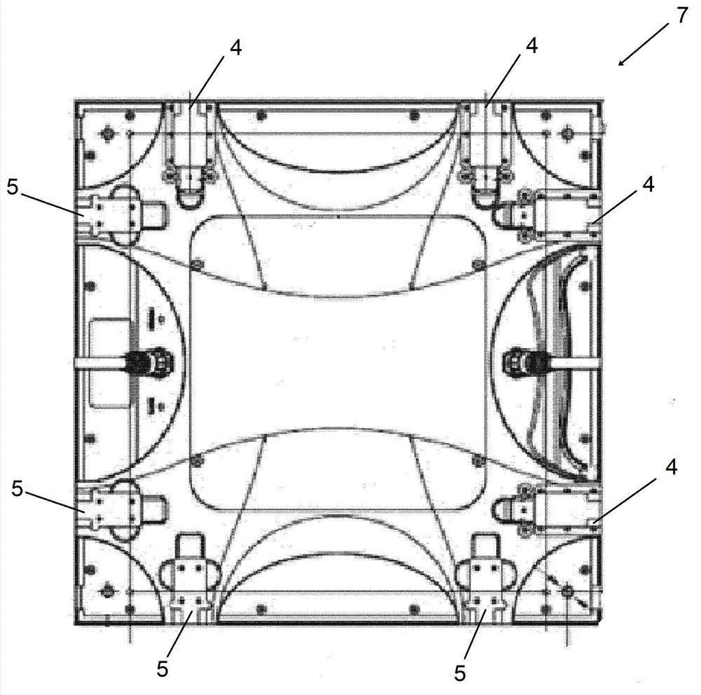
[0035] According to the LED display screen of the present invention, it mainly includes: a fixed bottom plate (such as Figure 6 shown), multiple LED modules, multiple connection devices. Wherein the LED module may include one or more LED lamps, a PCB board and a substrate, the LED lamp is installed on the front of the PCB board, the back of the PCB board is fixed on the substra...


PUM


Abstract

The invention relates an LED display screen, an LED module assembly and an assembling and disassembling method for the LED display screen. The LED display screen comprises the LED modules, at least a fixing baseplate used for fixing the LED modules, and connecting devices used for fixing the bottom surfaces of the LED modules on the front surfaces of the fixing base plates. Connecting devices comprise first connecting portions connected to the LED modules and second connecting portions connected to the fixing base plates, the first connecting portions and the second connecting portions are structured to enable the LED modules to be combined on the fixing base plates from the front side of the LED display screen, and joint connections between the first connecting portions and the second connecting portions are detachable. In addition, the invention further provides the LED module and the assembling and disassembling method for the LED display screen. Due to the above structure and the assembling and disassembling method for the LED display screen, the LED display screen is quite convenient to disassemble and assemble.

Description

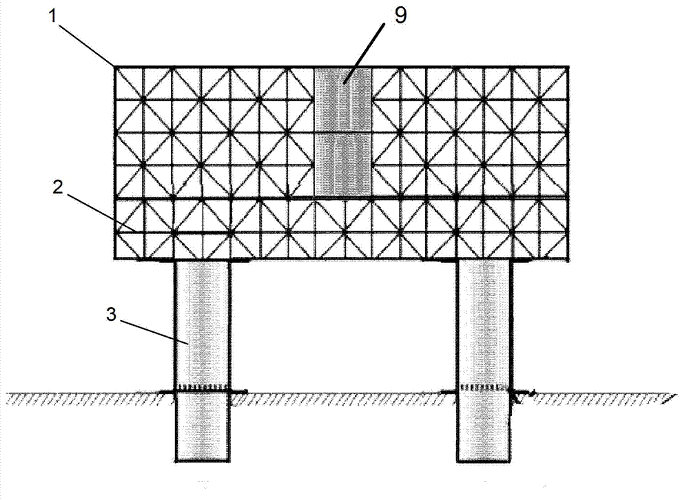
technical field [0001] The present invention relates to the installation of LED display screens, in particular to LED module components for assembling LED display screens and related assembly and disassembly methods, and in addition, the present invention also relates to LED display screens constructed from LED module components. Background technique [0002] At present, LED display assembly methods are generally divided into two types. One is to make a frame with materials such as aluminum alloy and steel, and fix the LED display module on the frame bottom plate with screws in a certain order. When fixing the LED module, the gap should be adjusted to ensure that the splicing is smooth. After the fixing is completed, various lines are connected. Finally, a frame is added and the rear panel is decorated. This is usually called frame installation. figure 1 It is a schematic diagram of the frame for outdoor installation. The frame 1 is constructed of channel steel 2 and suppor...

Claims


Application Information

Patent Timeline
Patent Type & Authority Applications(China)
IPC IPC(8): G09F9/33F16M13/02
Inventor 林开通
Owner 宁波凯睿信息技术咨询有限公司
Learn More