
Coupler paired wheel centering device and method

A coupling and center-finding technology, which is applied in the direction of measuring devices, mechanical devices, mechanical measuring devices, etc., can solve the problem of high labor costs for couplings to find wheels

Inactive Publication Date: 2020-03-27
华润电力(宜昌)有限公司
View PDF3 Cites 1 Cited by
  • Summary
  • Abstract
  • Description
  • Claims
  • Application Information

AI Technical Summary

Problems solved by technology

[0006] The main purpose of the present invention is to provide a device and method for finding the center of the alignment wheel of the coupling, aiming at solving the technical problem of the high labor cost of the alignment wheel of the coupling in the prior art

Method used


Image

  • Coupler paired wheel centering device and method
  • Coupler paired wheel centering device and method
  • Coupler paired wheel centering device and method

Examples


Embodiment Construction

[0033] It should be understood that the specific embodiments described here are only used to explain the present invention, not to limit the present invention.

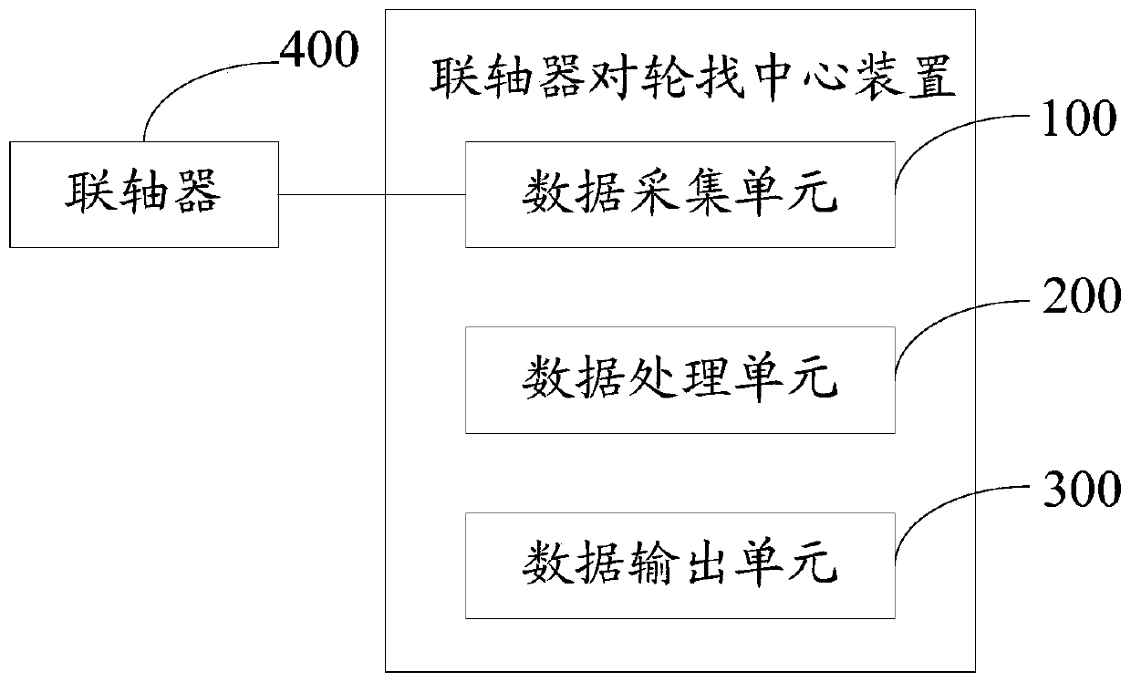
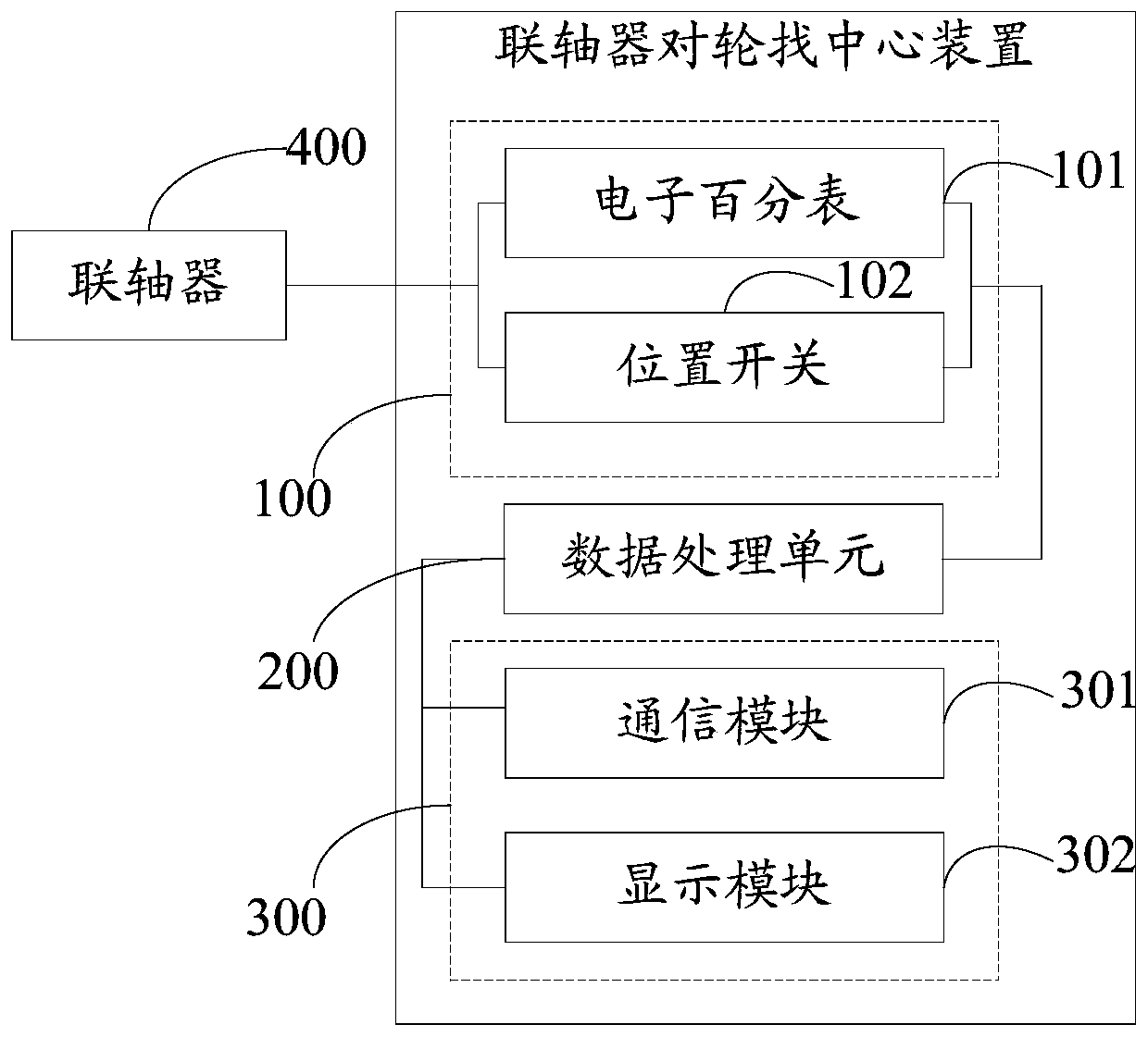
[0034] The embodiment of the present invention provides a device for finding the center of a coupling wheel, referring to figure 1 , figure 1 It is the first functional block diagram of the first embodiment of the centering device for the shaft coupling and wheels of the present invention. The device includes: a data acquisition unit 100 , a data processing unit 200 and a data output unit 300 . refer to figure 2 , figure 2 It is the second functional block diagram of the first embodiment of the centering device for the shaft coupling and wheels of the present invention.

[0035] The input end of the data acquisition unit 100 is connected to the preset position on the coupling surface, the output end of the data acquisition unit 100 is connected to the input end of the data processing unit 200, and the output of ...


PUM


Abstract

The invention relates to the technical field of coupler centering, and discloses a coupler paired wheel centering device and method. The device comprises a data acquisition unit, a data processing unit and a data output unit; the data acquisition unit is used for detecting the radial data and the axial data when the paired wheels of a coupler are centered, and sending the radial data and the axialdata to the data processing unit, the data processing unit is used for calculating a deviation value between the paired wheels of the current coupler according to the radial data and the axial data,generating a deviation adjustment scheme according to the deviation value and sending the deviation value and the deviation adjustment scheme to the data output unit, and the data output unit is usedfor displaying the deviation adjustment scheme to a user. The invention further provides a coupler paired wheel centering method which enables the labor efficiency to be improved, the equipment maintenance cost to be reduced, and the coupler centering precision to be improved.

Description

technical field [0001] The invention relates to the technical field of centering of a coupling, in particular to a centering device and method for a coupling and wheels. Background technique [0002] Couplings are mechanical general parts used to connect two shafts (driving shaft and driven shaft) in different mechanisms so that they rotate together to transmit torque. Couplings are used in high-speed and heavy-duty power transmission to play a role in buffering, shock absorption and improving the dynamic performance of the shafting. The coupling consists of two halves, which are respectively connected to the driving shaft and the driven shaft. Generally, the prime mover is mostly connected with the working machine by means of a coupling, and the coupling is the most commonly used connecting part for shaft transmission of mechanical products. [0003] Finding the center of the coupling is an important task in the maintenance of the rotating mechanical equipment in the powe...

Claims


Application Information

Patent Timeline
IPC IPC(8): G01B5/00G01B5/252
CPCG01B5/00G01B5/252
Inventor 肖益赵志坚张勇李旭毅唐忠阳冯启明
Owner 华润电力(宜昌)有限公司
Learn More