Steel-structure house top surface drainage structure and construction method thereof

A drainage structure and steel structure technology, which is applied to roofs, roof coverings, building structures, etc., can solve problems such as being unable to deal with blockage, not having a quick docking structure, and not having a water filtration structure.

Active Publication Date: 2020-03-27
CHINA CONSTR 4TH ENG BUREAU 6TH
View PDF9 Cites 2 Cited by
  • Summary
  • Abstract
  • Description
  • Claims
  • Application Information

AI Technical Summary

Problems solved by technology

[0005] In order to overcome the fact that the top drainage structure of the traditional steel structure house only has a single drainage structure, when the top drainage structure of the steel structure house is blocked, it cannot perform normal drainage operations. The design of the single drainage structure reduces the drainage of the top surface of the steel structure house. The drainage effect of the structure makes it unable to cope with the blocking situation; at the same time, the top drainage structure of the traditional steel structure house does not have a fast docking structure, which increases the time required for the installation and use of the top drainage structure of the steel structure house; The roof drainage structure of the structural house does not have a water body filtering structure, which makes it unable to filter impurities in the water body, so that the roof drainage structure of the steel structure house is prone to blockage during use, and a roof drainage structure of the steel structure house is provided

Method used


Image

  • Steel-structure house top surface drainage structure and construction method thereof
  • Steel-structure house top surface drainage structure and construction method thereof
  • Steel-structure house top surface drainage structure and construction method thereof

Examples


Embodiment Construction

[0028] The technical solutions in the embodiments of the present invention will be clearly and completely described below in conjunction with the embodiments of the present invention. Apparently, the described embodiments are only some of the embodiments of the present invention, not all of them. Based on the embodiments of the present invention, all other embodiments obtained by persons of ordinary skill in the art without creative efforts fall within the protection scope of the present invention.

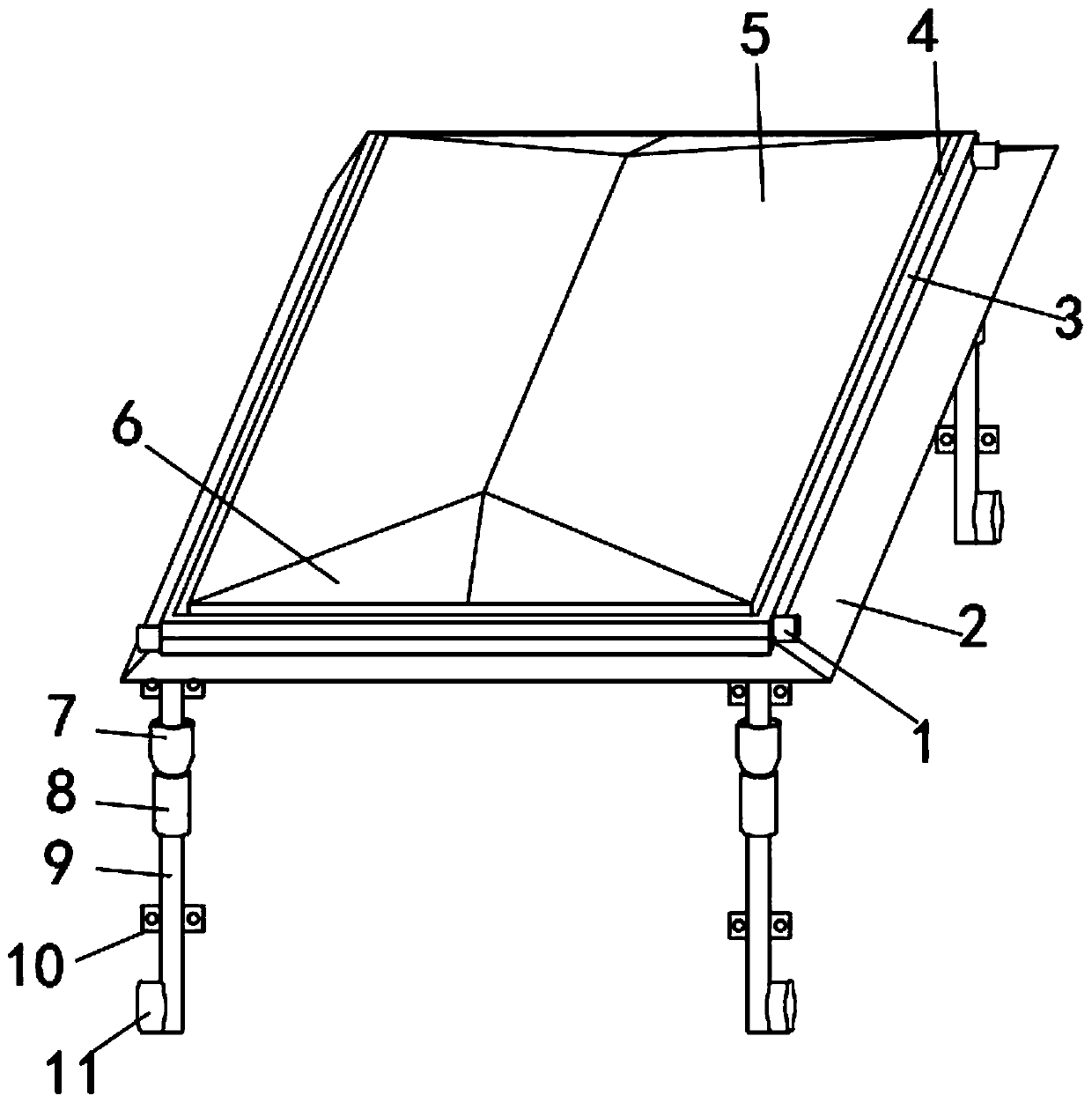
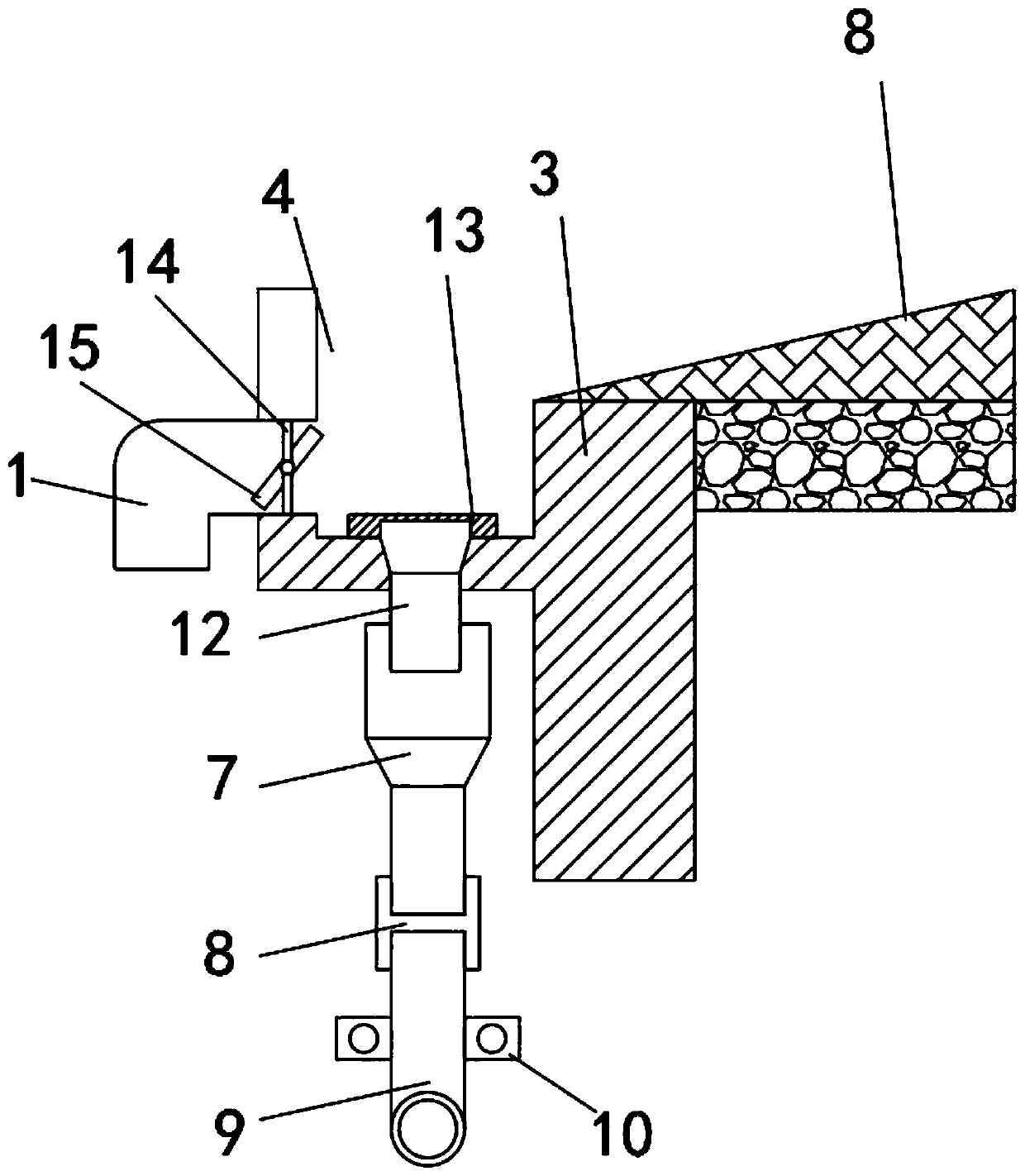
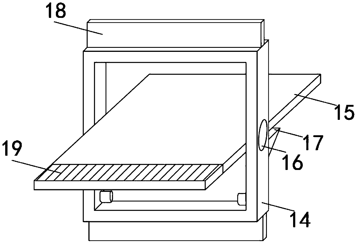
[0029] Such as Figure 1-5As shown, a roof drainage structure of a steel structure house includes a roof panel 3, a drainage pipe 9 and a fixed snap ring 14, the drainage pipe 9 is fixedly installed on the lower part of the roof panel 3, and the outer surface of the drainage pipe 9 is fixedly sleeved with The butt joint column 8, the outer surface of the upper end of the drain pipe 9 is fixedly socketed with a rainwater bucket 7, and the inner side of the bottom of the roof panel ...


PUM


Abstract

The invention discloses a steel-structure house top surface drainage structure. The structure comprises a roof panel, a drainage pipe and a fixed clamping ring; the drainage pipe is fixedly mounted atthe lower part of the roof panel; the outer surface of the drainage pipe is fixedly sleeved with a butt joint sleeve column, and the outer surface of the upper end of the drainage pipe is fixedly sleeved with a rainwater hopper; the inner side of the bottom of the roof panel is fixedly sleeved with a water outlet pipe; the water outlet pipe and the water drainage pipe are butted and fixed througha rainwater hopper; a drainage channel is formed in the inner side of the upper portion of the roof panel, the fixed clamping ring is fixedly installed on the side, close to the drainage channel, ofthe inner surface of the upper portion of the roof panel, a second receiving hopper is fixedly installed on the outer surface of the upper end of the butt joint sleeve column, and a first receiving hopper is fixedly installed on the outer surface of the lower end of the butt joint sleeve column. According to the steel-structure house top face drainage structure, the structure has an auxiliary drainage structure, the functionality of the steel-structure house top face drainage structure is improved, the blocking phenomenon of the steel-structure house top face drainage structure is avoided, andthe operation difficulty during pipeline butt-joint installation is reduced.

Description

technical field [0001] The invention belongs to the technical field of drainage structures, and in particular relates to a roof drainage structure of a steel structure house, more specifically a roof drainage structure of a steel structure house and a construction method thereof. Background technique [0002] The roof drainage structure of the steel structure house is a drainage structure used on the roof of the house. The rainwater on the roof of the house can be collected and discharged by using the drainage structure, thereby avoiding the phenomenon of water accumulation on the roof of the house. [0003] The comparative document CN208899769U discloses a roof drainage structure, the technical solution is as follows: it includes a drainage ditch extending downwards, the end of the drainage ditch is inclined downwards, and there is a drainage outlet connected to the building drainage system, and the drainage outlet is covered with a filter element. It also includes a runner...

Claims


Application Information

Patent Timeline
IPC IPC(8): E04D13/064E04D13/076
CPCE04D13/064E04D13/0645E04D13/0767
Inventor 向俊志翟光耀杨海波胡晓梅刘芳玲
Owner CHINA CONSTR 4TH ENG BUREAU 6TH
Why Eureka
Try Eureka