Cloth inspecting machine convenient for cloth installation

A cloth inspection machine and fabric technology, applied in the field of cloth inspection machines, can solve problems such as affecting the efficiency of cloth inspection, laborious and laborious operation, affecting production efficiency, etc.

Inactive Publication Date: 2020-03-27
义乌市尼美机械加工厂
View PDF0 Cites 3 Cited by
  • Summary
  • Abstract
  • Description
  • Claims
  • Application Information

AI Technical Summary

Problems solved by technology

[0003] The traditional fabric inspection machine needs to manually install the fabric. When installing the fabric, one end of the fabric needs to be drawn out manually, then passed through multiple conveying rollers, and finally wound on the roll frame. The operation is laborious and laborious, which seriously affects the fabric inspection. Therefore, a cloth inspection machine that is convenient for cloth installation and can automatically roll up the cloth is proposed to solve the above problems

Method used


Image

  • Cloth inspecting machine convenient for cloth installation
  • Cloth inspecting machine convenient for cloth installation
  • Cloth inspecting machine convenient for cloth installation

Examples


Embodiment 1

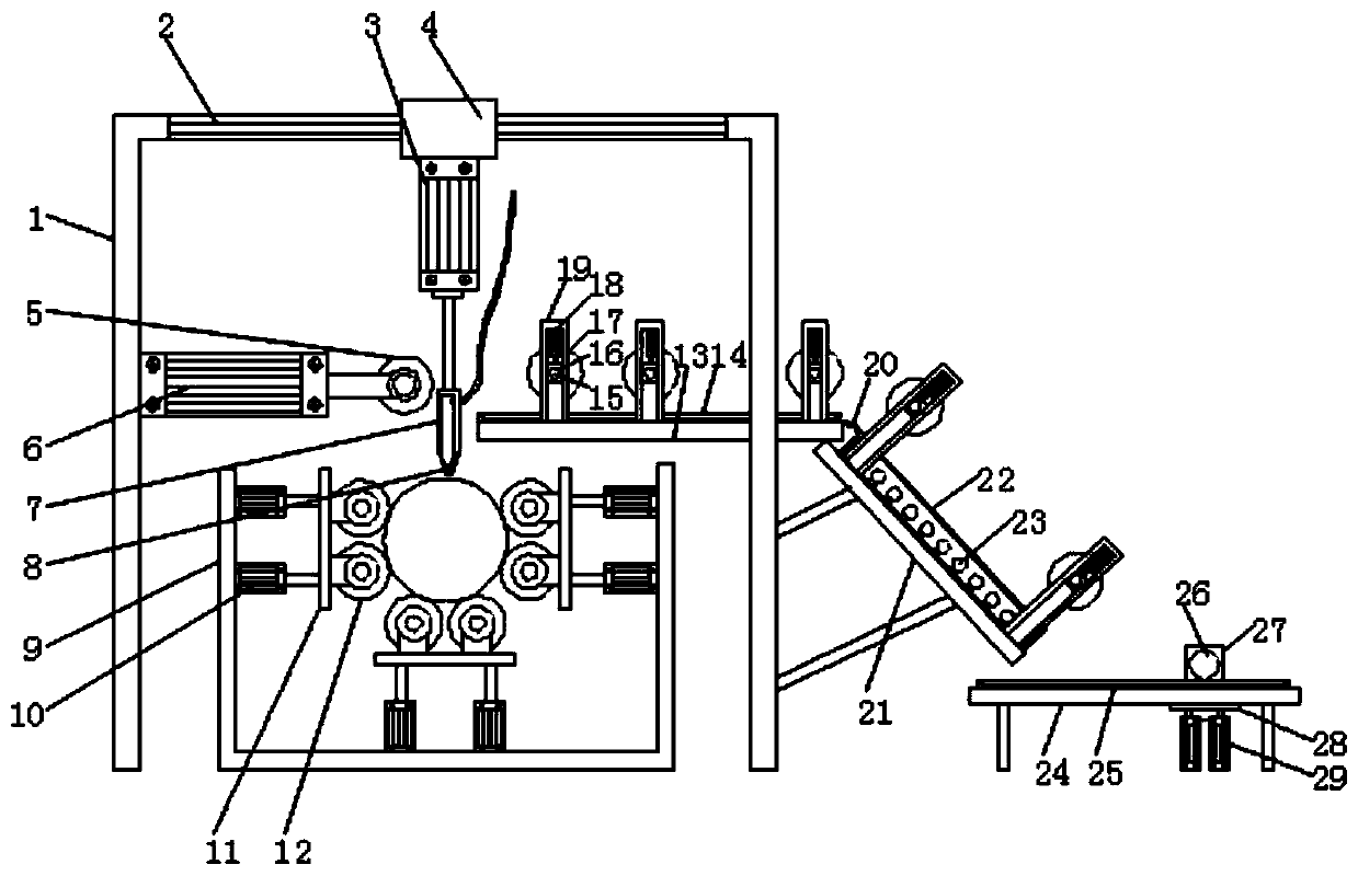
[0026] Embodiment one, with reference to figure 1 and Figure 3-4 , a cloth inspecting machine for convenient cloth installation, comprising a door frame 1 and an installation groove 9, an installation groove 9 is arranged under the door frame 1, and an installation plate 11 is connected to the inner wall of the installation groove 9 through a third cylinder 10, and the three sides of the installation plate 11 distribution, and a stabilizing roller 12 is installed on one side of the mounting plate 11, a cloth roll is placed between the stabilizing rollers 12, and the third cylinder 10 is stretched to push the stabilizing roller 12 to be squeezed and fixed to prevent the cloth from falling, and the door frame 1 top A lead screw 2 is fixedly installed on the surface, and the surface of the lead screw 2 is provided with a moving block 4, which is a common structure of the lead screw 2, and will not be repeated here, and the bottom surface of the moving block 4 is connected with a...

Embodiment 2

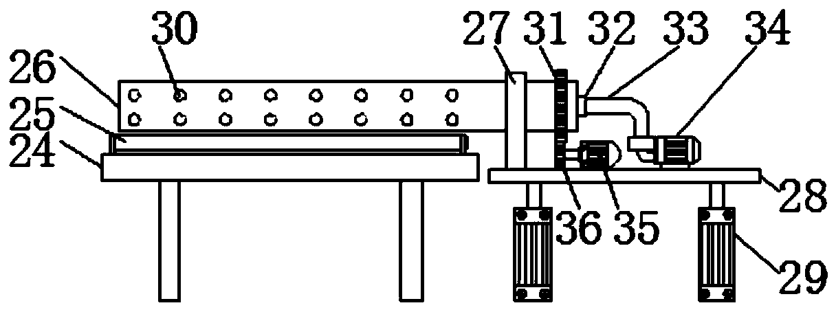
[0027] Embodiment two, refer to Figure 1-2, a third platform 24 is provided below the light box 22, and a second conveyor belt 25 is installed on the top surface of the third platform 24, and a winding roller 26 is arranged above the other end of the second conveyor belt 25, and the third platform 24 is passed through the fifth cylinder 29 is equipped with a bearing plate 28, and the top surface of the bearing plate 28 is fixedly equipped with a motor 35 and a vacuum pump 34, and one end of the rolling roller 26 is located above the bearing plate 28 and is sleeved with a gear ring 31, and the bottom surface of the gear ring 31 is engaged with a gear 36, and The gear 36 is fixedly connected with the output end of the motor 35, and the other end of the rolling roller 26 is connected with an air extraction pipe 33 through a sealed bearing 32. When the rolling roller 26 is rotating, the air extraction pipe 33 does not rotate, and the sealing bearing 32 prevents air leakage. The c...

Embodiment 3

[0028] Embodiment three, refer to Figure 1-3 The surfaces of the first press roller 5, the second press roller 17, the first conveyor belt 14 and the second conveyor belt 25 are all rough structures to prevent the cloth from slipping off, and an arc plate 20 is fixedly connected between the first platform 13 and the second platform 21, And the surface of the arc plate 20 is a smooth structure, which is convenient for the cloth to slide from the first platform 13 to the top surface of the light box 22, the first cylinder 3, the second cylinder 6, the third cylinder 10, the fourth cylinder 18, the fifth cylinder 29, and the motor 35 , the motor 37, the vacuum pump 34, the input terminals of the first conveyor belt 14 and the second conveyor belt 25 are all electrically connected to the output terminal of the control switch, because the control structure is relatively common, so it will not be repeated here.

[0029] Working principle: move the device to a suitable position, tur...


PUM


Abstract

The invention discloses a cloth inspecting machine convenient for cloth installation. The cloth inspecting machine comprises a door frame and an installation groove, the installation groove is formedin the lower part of the door frame, an installation plate is connected to the inner wall of the installation groove through a third air cylinder, stabilizing rollers are installed on the surface of one side of the installation plate, a lead screw is fixedly installed on the top surface of the door frame, a moving block is arranged on the surface of the lead screw, and a sucking plate is connectedto the bottom surface of the moving block through a first air cylinder. According to the cloth inspecting machine, firstly, the first air cylinder, a second air cylinder, the sucking plate, the leadscrew, a first pressure roller and a second pressure roller are adopted, in the use of the cloth inspecting machine, a worker only needs to place the cloth between the stabilizing rollers, and make one end of a cloth roll, namely the leading end of the cloth, align with the right lower part of the sucking plate to complete the cloth inspection, the installation is very convenient and fast, the cloth inspection efficiency is greatly improved, secondly, a coiling roller, a vacuum pump and a fifth air cylinder are adopted, thus automatic coiling is conducted on the cloth inspecting machine aftercloth inspection, operation is convenient, cloth scattering is avoided, and the carrying and later use are facilitated for the worker.

Description

technical field [0001] The invention relates to the technical field of cloth inspecting machines, in particular to a cloth inspecting machine which is convenient for cloth installation. Background technique [0002] The cloth inspecting machine is a set of necessary special equipment for inspecting cotton, wool, hemp, silk, chemical fiber and other large-format, double-width and single-width cloths before production in the garment industry. The cloth inspection machine automatically completes the work of recording length and packaging , with an electronic defect detection device, which is statistically analyzed by a computer to assist in the cloth inspection operation and print out. [0003] The traditional fabric inspection machine needs to manually install the fabric. When installing the fabric, one end of the fabric needs to be drawn out manually, then passed through multiple conveying rollers, and finally wound on the roll frame. The operation is laborious and laborious,...

Claims


Application Information

Patent Timeline
Patent Type & Authority Applications(China)
IPC IPC(8): B65H19/28B65H18/10D06H3/06
CPCB65H18/10B65H19/28B65H2301/41426D06H3/06
Inventor 乔辉王起任大龙
Owner 义乌市尼美机械加工厂
Why Eureka
Try Eureka