
Splicing and pressure-maintaining device for wooden furniture

A pressure-maintaining device and a technology for wooden furniture, which are applied in the joining of wooden veneers, manufacturing tools, and wood processing appliances, etc., can solve the problems of uneven force, skewed joints, inconvenience, etc., and achieve the loading and pressure-maintaining operation. The process is labor-saving and the pressure is reliable.

Active Publication Date: 2020-03-27
福州立雅家具有限公司
View PDF5 Cites 0 Cited by
  • Summary
  • Abstract
  • Description
  • Claims
  • Application Information

AI Technical Summary

Problems solved by technology

In production, most of the existing tightening and pressure-holding devices use clamps, which are extremely inconvenient to use, and the force is uneven, resulting in skewed joints
Second, clamps are often not available for larger furniture structures

Method used


Image

  • Splicing and pressure-maintaining device for wooden furniture
  • Splicing and pressure-maintaining device for wooden furniture
  • Splicing and pressure-maintaining device for wooden furniture

Examples


Embodiment 1

[0078] Please refer to Figure 1 to Figure 4 , Embodiment 1 of the present invention is:

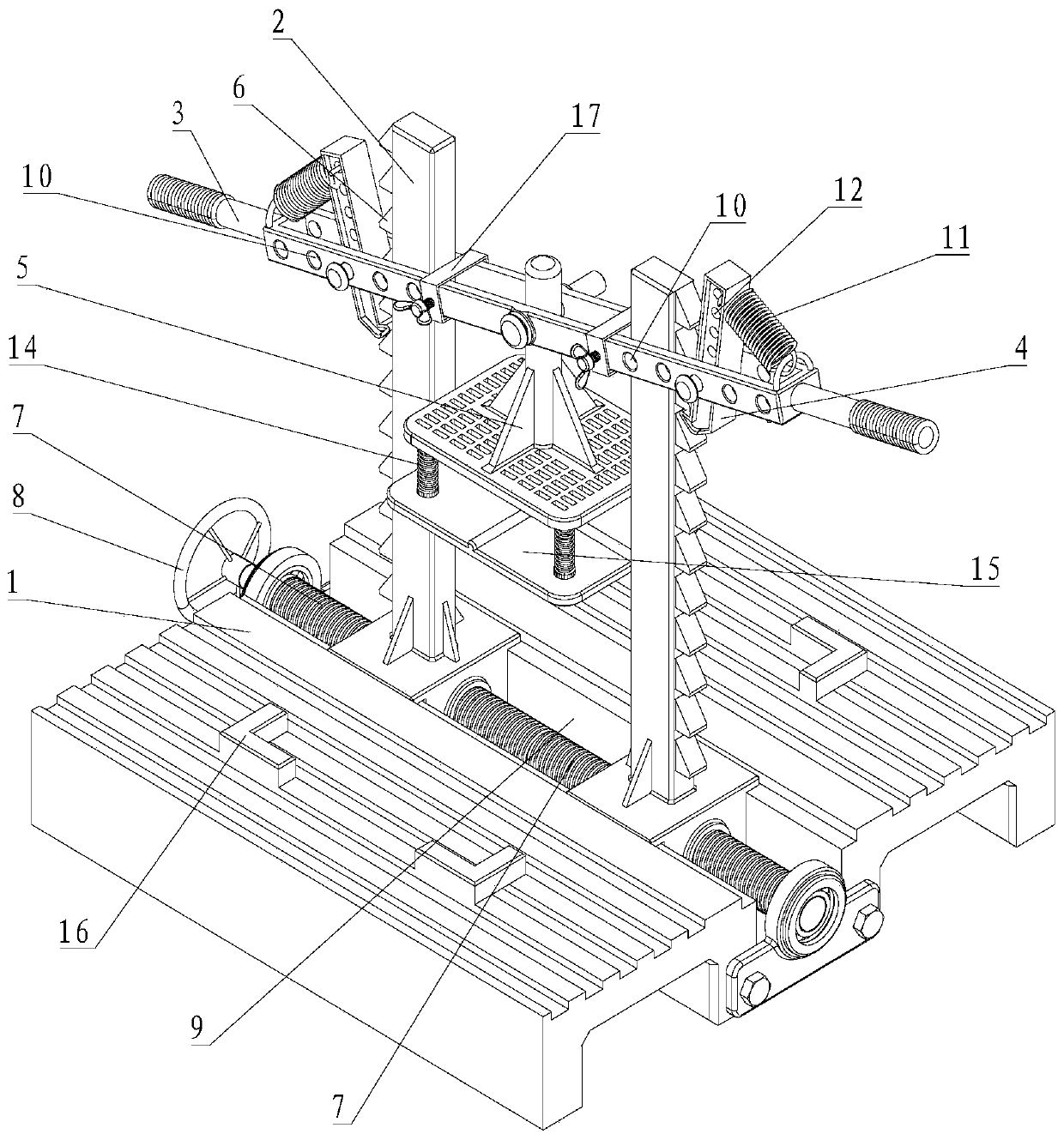
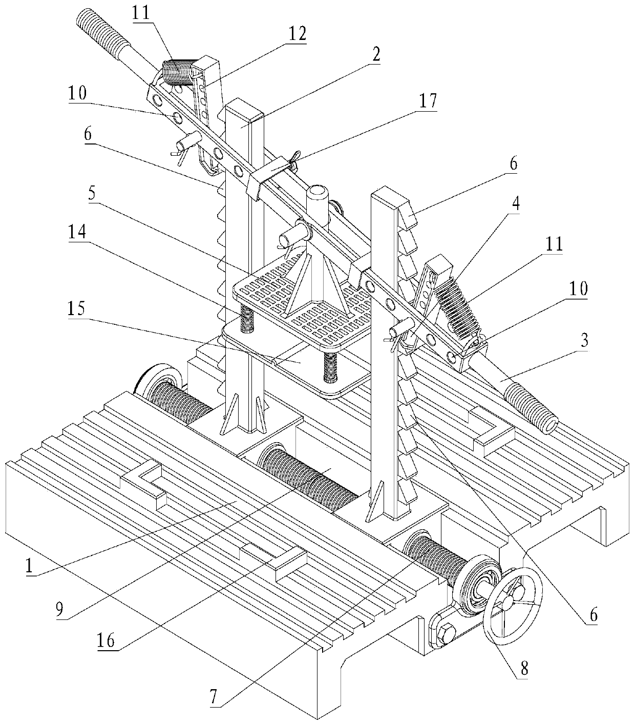
[0079] A splicing and pressure maintaining device for wooden furniture, comprising a tooling table 1, a lifting frame 2, a rocker 3, a claw hook 4 and a loading table 5;

[0080] The lifting frame 2 includes two;

[0081] The two lifting frames 2 are relatively arranged on the tooling table 1;

[0082] The lifting frame 2 is perpendicular to the working surface of the tooling table 1;

[0083] A plurality of successively arranged lifting teeth 6 are respectively arranged on the sides opposite to each other on the two lifting frames 2 along the vertical direction;

[0084] The upper surface of the lifting tooth 6 is a wedge surface; the lower surface of the lifting tooth 6 is a plane parallel to the horizontal direction;

[0085] The rocker 3 is sleeved on the two lifting frames 2 so as to move up and down;

[0086] The claw hook 4 includes two;

[0087] One end of the claw hook 4 i...

Embodiment 2

[0107] Please refer to Figure 5 to Figure 8 , the second embodiment of the present invention is:

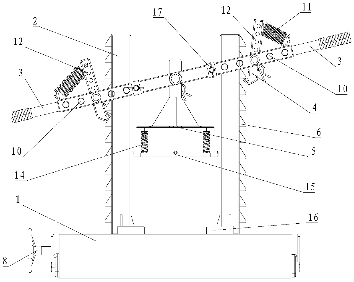
[0108] A splicing and pressure maintaining device for wooden furniture, comprising a tooling table 1, a lifting frame 2, a rocker 3, a claw hook 4 and a loading table 5;

[0109] The lifting frame 2 includes two;

[0110] The two lifting frames 2 are relatively arranged on the tooling table 1;

[0111] The lifting frame 2 is perpendicular to the working surface of the tooling table 1;

[0112] On the opposite sides of the two lifting frames 2, a plurality of lifting teeth 6 arranged in sequence are respectively arranged along the vertical direction;

[0113] The upper surface of the lifting tooth 6 is a wedge surface; the lower surface of the lifting tooth 6 is a plane parallel to the horizontal direction;

[0114] The rocker 3 is sleeved on the two lifting frames 2 so as to move up and down;

[0115] The claw hook 4 includes two;

[0116] Each lifting frame 2 is provided ...


PUM


Abstract

The invention provides a splicing and pressure-maintaining device for wooden furniture. The splicing and pressure-maintaining device comprises a worktable, two lifting frames, a rocker, claw hooks anda loading table; a plurality of lifting teeth arrayed in sequence are separately arranged on sides back to or opposite to each other of the two lifting frames in the vertical direction; the upper surfaces of the lifting teeth are inclined wedge surfaces; the lower surfaces of the lifting teeth are planes parallel to the horizontal direction; the rocker is arranged on the lifting frames in a vertically moving manner; ends of the claw hooks are hinged to one end of the rocker; the other ends of the claw hooks can move vertically along the lifting teeth, and are in contact with gaps between different lifting teeth under the elastic action; the loading table is hinged to the middle position of the rocker; and the contact surface of the loading table is parallel to the working surface of a tool table. The splicing and pressure-maintaining device meets the condition of saving labor through a lever, and the loading and pressure-maintaining operation process is more labor-saving.

Description

technical field [0001] The invention relates to the technical field of wood product processing equipment, in particular to a splicing and pressure maintaining device for wooden furniture. Background technique [0002] Most of the splicing structures used in wooden furniture processing are mortise and tenon structures; the existing processing technology often paints adhesives on the splicing structures, the reason is that in mass production and processing, the matching dimensions of tenon and tenon structures will not It is very tight. In order to facilitate quick assembly, it is necessary to apply adhesive to ensure that the connection at the joint is firmly fixed. Due to the use of adhesives, it is necessary to carry out a period of pressure-holding treatment after the splicing, so that the adhesive can achieve the best bonding effect after the pressure-holding treatment, so that the splicing structure of the furniture is firmly connected. In production, most of the existi...

Claims


Application Information

Patent Timeline
IPC IPC(8): B27D1/10B27D3/00
CPCB27D1/10B27D3/00
Inventor 林义雄
Owner 福州立雅家具有限公司
Learn More