Multi-station rotary disc type automatic assembly production line of combined roller

An automatic assembly and multi-station technology, applied in assembly machines, metal processing, manufacturing tools, etc., can solve the problems of large production area, many parts, and complex structure of automatic assembly line

Pending Publication Date: 2020-03-27
无锡阿尔法精密机械制造有限公司
View PDF1 Cites 15 Cited by
  • Summary
  • Abstract
  • Description
  • Claims
  • Application Information

AI Technical Summary

Problems solved by technology

[0004] Although the above technical solution can realize the automatic assembly of combined rollers, the structure of the entire automatic assembly production line is relatively complicated and the layout is unreasonable
First of all, the conveying mechanism and assembly mechanism of each component of the combined roller are arranged in a straight line, which occupies a large production area; secondly, the conveying stroke of each component is longer, which increases the probability of material jamming during the conveying process, which is not conducive to The automatic assembly is normally carried out; thirdly, there are many parts in the conveying mechanism and assembly mechanism of the combined roller, which leads to an increase in the failure rate of the production line, which is not convenient for the staff to maintain, and also increases the equipment cost; fourth, the various parts of the combined roller The components may not be assembled properly during the assembly process, and there is no technical solution to solve this technical problem in the above patent

Method used


Image

  • Multi-station rotary disc type automatic assembly production line of combined roller
  • Multi-station rotary disc type automatic assembly production line of combined roller
  • Multi-station rotary disc type automatic assembly production line of combined roller

Examples


Embodiment Construction

[0052] The present invention will be described in further detail below in conjunction with the accompanying drawings.

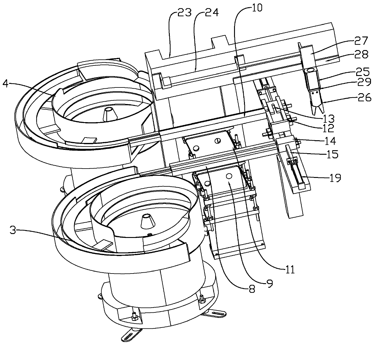
[0053] Such as figure 1 and 2 As shown, the present invention mainly includes a turntable 1, a bolt feeding mechanism, a bearing feeding mechanism, a gasket feeding mechanism, a collar feeding mechanism, a press-fitting mechanism and a turntable unloading mechanism.

[0054] Such as figure 1 and 2 As shown, the bolt feeding mechanism, the bearing feeding mechanism, the gasket feeding mechanism, the collar feeding mechanism, the press-fitting mechanism and the turntable unloading mechanism are arranged around the turntable 1 in sequence. There is a bearing seat 2 in the area of ​​the ring feeding mechanism, the press-fitting mechanism and the turntable blanking mechanism, and the top of the turntable 1 faces the area between the press-fit mechanism and the turntable blanking mechanism, and the top of the turntable 1 faces the pad feeding The area between t...


PUM


Abstract

The invention relates to a combined roller and particularly relates to a multi-station rotary disc type automatic assembly production line of the combined roller. The combined roller comprises a rotary disc, a bolt feeding mechanism, a bearing feeding mechanism, a gasket feeding mechanism, a clamping ring feeding mechanism, a press fitting mechanism and a rotary disc discharging mechanism, whereinthe rotary disc is connected with a rotation driving mechanism, the rotation driving mechanism can drive the rotary disc to rotate, the bolt feeding mechanism, the bearing feeding mechanism, the gasket feeding mechanism, the clamping ring feeding mechanism, the press fitting mechanism and the rotary disc discharging mechanism are sequentially arranged on the periphery of the rotary disc, and bearing seats are arranged at area positions, facing the bolt feeding mechanism, the gasket feeding mechanism, the clamping ring feeding mechanism, the press fitting mechanism and the rotary disc discharging mechanism, of an upper face of the rotary disc respectively. The combined roller is advantaged that the conveying mechanism and the assembling mechanism of all parts of a combined roller are distributed along the rotary disc, so the combined roller is continuously and automatically assembled in a relatively concentrated area, the occupied production area is small, and production cost is reduced.

Description

technical field [0001] The invention relates to a combination roller, in particular to a multi-station turntable automatic assembly production line for the combination roller. Background technique [0002] A combination roller is needed in the car door handle, such as figure 1 As shown, the combined roller includes bolts, rollers, gaskets and collars, and the bolts, rollers, gaskets and collars need to be pressed together during assembly. When the combination roller is assembled, firstly, the roller is set on the nut section of the bolt, and the gasket is set on the screw section of the bolt, and the gasket is located on the upper surface of the roller. In order to make the bolt, the roller and the gasket press Put them together, and then set the collar on the screw section of the bolt, and the staff will press the collar to the side close to the gasket, so that the collar and the gasket fit together, and the teeth of the collar are stuck between the adjacent two Between t...

Claims


Application Information

Patent Timeline
IPC IPC(8): B23P21/00B23P19/00
CPCB23P19/001B23P21/006
Inventor 马富民
Owner 无锡阿尔法精密机械制造有限公司
Why Eureka
Try Eureka