
Plasma jet switch

A plasma and switch technology, applied in the field of plasma jet, can solve the problems of low plasma jet height, high output impedance of trigger pulse, false trigger and many malfunctions, etc., so as to improve the trigger effect, reduce the impact, and reduce the output impedance Effect

Active Publication Date: 2021-02-26
XI AN JIAOTONG UNIV
View PDF12 Cites 0 Cited by
  • Summary
  • Abstract
  • Description
  • Claims
  • Application Information

AI Technical Summary

Problems solved by technology

[0002] For the overcurrent protection of the DC power grid, the mechanical switch currently used has a too long start-up time, and the existence of the existing gas switch leads to high output impedance of the trigger pulse, low plasma injection height, and more false triggers and malfunctions. , the problem of low reliability

Method used


Image

  • Plasma jet switch
  • Plasma jet switch

Examples


Embodiment Construction

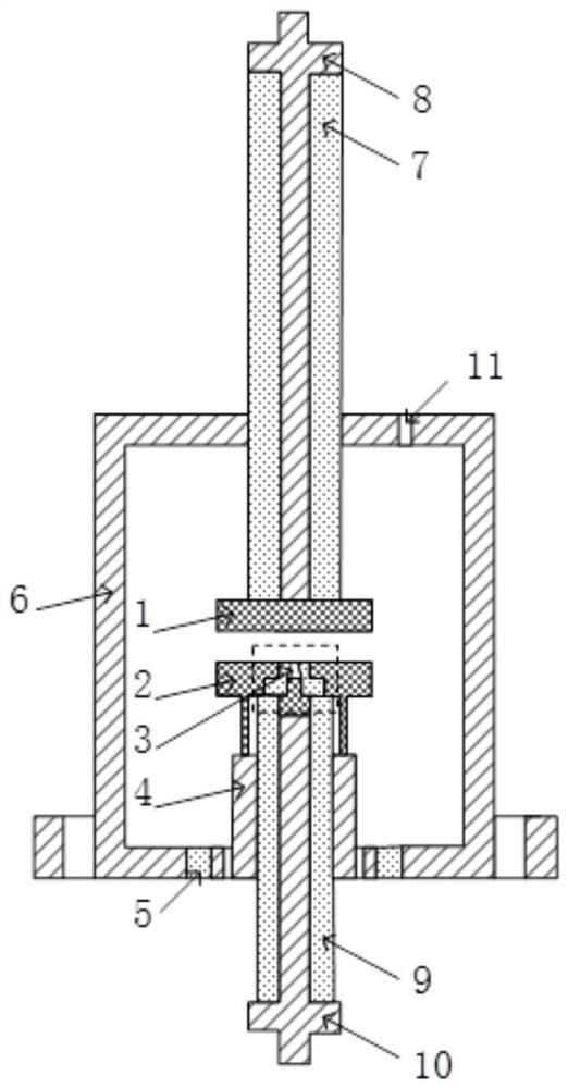
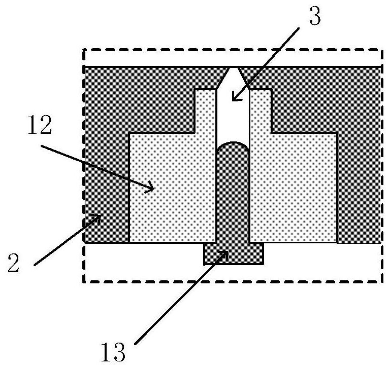
[0032] The following will refer to the attached Figure 1 to Figure 2 Specific examples of the present invention are described in more detail. Although specific embodiments of the invention are shown in the drawings, it should be understood that the invention may be embodied in various forms and is not limited to the embodiments set forth herein. Rather, these embodiments are provided for more thorough understanding of the present invention and to fully convey the scope of the present invention to those skilled in the art.

[0033] It should be noted that certain terms are used in the specification and claims to refer to specific components. Those skilled in the art should understand that they may use different terms to refer to the same component. The specification and claims do not use differences in nouns as a way of distinguishing components, but use differences in functions of components as a criterion for distinguishing. "Includes" or "comprises" mentioned throughout ...


PUM


Abstract

A plasma jet switch is disclosed. In the plasma jet switch, the casing includes a first opening and a second opening, the first main electrode is connected to the first connecting rod and is located in the casing, the first insulating ring is sleeved in the second opening, and the stainless steel The cylinder covers the second opening and isolates the shell through the first insulating ring. The second main electrode is connected to the stainless steel cylinder and is located in the shell. The second main electrode is arranged at a distance from the first main electrode. The side away from the first main electrode is provided with an excitation cavity with a nozzle, the needle electrode is connected to the second connecting rod and is located in the shell, and the head of the needle electrode is wrapped by a second insulating ring in the excitation cavity, The part other than the head of the needle electrode is wrapped by the second sleeve, the head of the needle electrode, the second insulating ring and the second main electrode wall with the nozzle constitute the injection chamber, and the second connecting rod receives the trigger pulse A creeping discharge is formed in the injection cavity.

Description

technical field [0001] The invention relates to the field of plasma jet technology, in particular to a plasma jet switch. Background technique [0002] For the overcurrent protection of the DC power grid, the mechanical switch currently used has a too long start-up time, and the existence of the existing gas switch leads to high output impedance of the trigger pulse, low plasma injection height, and more false triggers and malfunctions. , the problem of low reliability. [0003] The above information disclosed in this Background section is only for enhancement of understanding of the background of the invention and therefore it may contain information that does not form the prior art that is already known in the art to a person of ordinary skill in the art. Contents of the invention [0004] In order to solve the above-mentioned problems, the present invention provides a plasma jet switch. The purpose of the present invention is to be achieved through the following techn...

Claims


Application Information

Patent Timeline
Patent Type & Authority Patents(China)
IPC IPC(8): H05H1/26
CPCH05H1/26
Inventor 李晓昂刘轩东郜淦吕玉芳任蔷孙昊晨李杰张乔根
Owner XI AN JIAOTONG UNIV
Learn More