
Inductive coil driving circuit with protection function

A protection function and coil driving technology, which is applied to electromagnets with armatures, circuits, electromagnetic circuit devices, etc., can solve problems such as inability to drive low-impedance coils, high coil drive voltage, and insufficient drive capacity, and achieve accurate and effective fault detection means, enhanced reliability, effective and reliable control and effectiveness of protection mechanisms

Pending Publication Date: 2020-03-24
天索(苏州)控制技术有限公司
View PDF0 Cites 1 Cited by
  • Summary
  • Abstract
  • Description
  • Claims
  • Application Information

AI Technical Summary

Problems solved by technology

[0003] 1. The cost of contactors using high coil voltage will increase;
[0004] 2. The driving voltage of the coil is high, and there will be safety hazards
In addition, PWM inductive coil drive is also required for applications such as electromagnetic brakes and proportional valves. However, due to the high driving voltage and large current, different failure modes usually occur:
[0006] 1. Insufficient drive capability to drive low impedance coils;
[0007] 2. When the coil is short-circuited, it will cause an instantaneous large current in the drive circuit and cause overcurrent damage to the power device;
[0008] 3. Lack of comprehensive fault detection methods for various failure modes of contactors (short circuit / open circuit of coils and contacts)

Method used


Image

  • Inductive coil driving circuit with protection function
  • Inductive coil driving circuit with protection function
  • Inductive coil driving circuit with protection function

Examples


Embodiment Construction

[0026] In order to make the above objects, features and advantages of the present invention more comprehensible, specific implementations of the present invention will be described in detail below in conjunction with the accompanying drawings. In the following description, numerous specific details are set forth in order to provide a thorough understanding of the present invention. However, the present invention can be implemented in many other ways different from those described here, and those skilled in the art can make similar improvements without departing from the connotation of the present invention, so the present invention is not limited by the specific embodiments disclosed below.

[0027] It should be noted that when an element is referred to as being “disposed on” another element, it may be directly on the other element or there may also be an intervening element. When an element is referred to as being "connected to" another element, it can be directly connected t...


PUM


Abstract

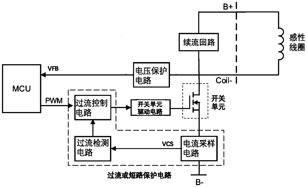
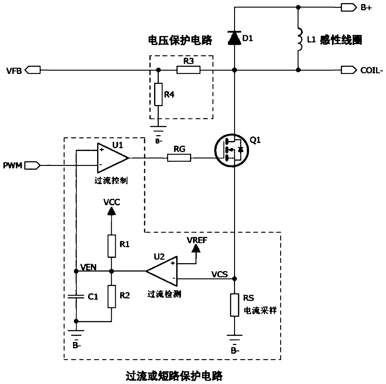
The invention relates to an inductive coil drive circuit with a protection function. The circuit comprises an inductive coil, a follow current loop, a switch unit, a switch unit driving circuit, a main control unit and an overcurrent or short circuit protection circuit, after the inductive coil is connected in parallel with the follow current loop, one end is connected with one end of bus voltage,the other end is connected with the first end of the switch unit; the second end of the switch unit is connected with the other end of the bus voltage; the third end of the switch unit is connected with the main control unit through the switch unit driving circuit; a control signal sent by the main control unit is received, one end of the overcurrent or short-circuit protection circuit is connected with the other end of the bus voltage, the other end of the overcurrent or short-circuit protection circuit is connected between the main control unit and the switch unit driving circuit, and the two ends of the inductive coil serve as output ends to output driving voltage. By utilizing current feedback and voltage feedback, an effective and reliable control and protection mechanism is provided.

Description

technical field [0001] The invention relates to the technical field of motor controllers for medium and low-speed electric vehicles and special engineering vehicles, in particular to a contactor control coil drive circuit. Background technique [0002] For medium and low-speed electric vehicles and special engineering vehicles (such as forklifts, etc.), the power battery voltage is generally between 48V and 96V, and there is often no battery to provide 12V driving voltage. For the contactor control commonly used in the vehicle, the most common 12V coil voltage contactor cannot be used, but only the contactor with the same bus voltage as the one used, which causes the following two disadvantages: [0003] 1. The cost of contactors using high coil voltage will increase; [0004] 2. The driving voltage of the coil is high, which may cause potential safety hazards. [0005] In view of the above deficiencies, if the PWM coil driving method is adopted, different driving voltages...

Claims


Application Information

Patent Timeline
IPC IPC(8): H01H47/00H01H47/32H01F7/18H01F7/06
CPCH01F7/064H01F7/1844H01H47/002H01H47/325
Inventor 朱利东陈峰
Owner 天索(苏州)控制技术有限公司
Learn More