
A magnetically coupled transmission numerically controlled plug

A technology of plugging and magnetic coupling, applied in wellbore/well components, production fluid, sealing/isolation, etc., can solve complex dynamic sealing structure and processing cost, high flow control accuracy, high pressure at the valve outlet, etc. problems, to achieve the effect of improving system reliability, high flow control accuracy, and reducing sealing difficulty

Active Publication Date: 2020-09-22
NORTHEAST GASOLINEEUM UNIV
View PDF5 Cites 0 Cited by
  • Summary
  • Abstract
  • Description
  • Claims
  • Application Information

AI Technical Summary

Problems solved by technology

[0003] In order to solve the technical problems mentioned in the background technology, the present invention provides a magnetic coupling transmission digital control plug, which uses magnetic coupling transmission technology to convert dynamic seals into static seals, avoiding complicated dynamic seals The problem of structure and processing cost greatly reduces the difficulty of sealing, and combines the magnetic transmission technology and the absolute value encoder to control the absolute position of the valve core to realize the dynamic balance of the pressure at the valve, and solve the problem of the blockage caused by the high pressure at the outlet of the valve during the water distribution process. The problem of turning, and realize the purpose of numerical control to adjust the flow, the flow control accuracy is high

Method used


Image

  • A magnetically coupled transmission numerically controlled plug
  • A magnetically coupled transmission numerically controlled plug
  • A magnetically coupled transmission numerically controlled plug

Examples


Embodiment Construction

[0017] The present invention will be further described below in conjunction with accompanying drawing:

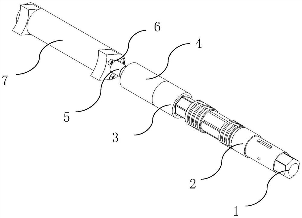
[0018] figure 1 As shown, the magnetic coupling transmission numerical control plug includes a numerical control plug body 2, a lower plug 1, a titanium alloy plug 3, a permanent magnet fixing sleeve 4, a coupling 5, a cross recessed countersunk head screw 6 and a high Torque DC Motor Housing7.

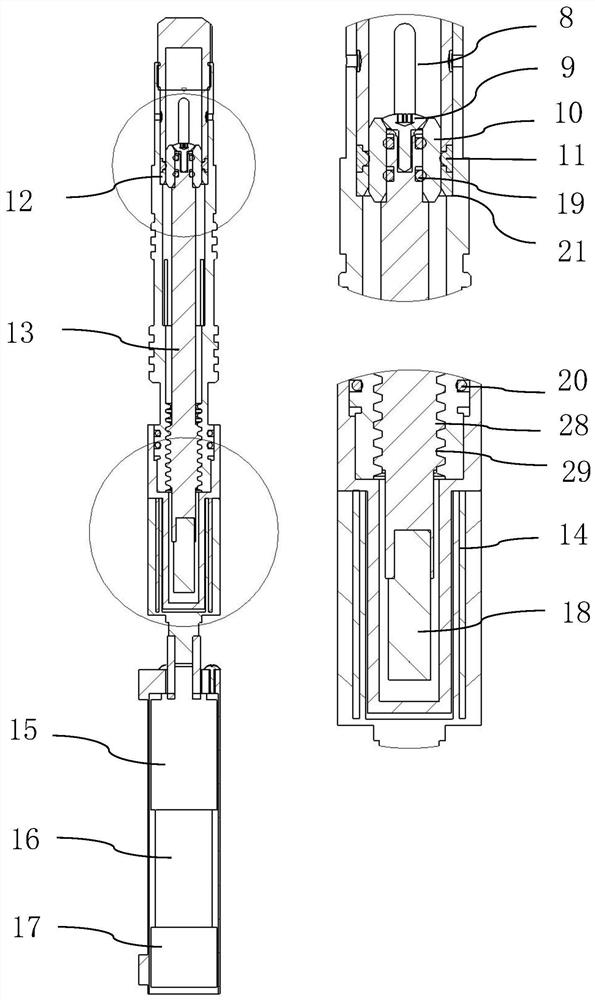
[0019] figure 2 Shown is the overall cross-sectional view and partial enlarged view of the magnetic coupling transmission digital control plug of the present invention. Depend on figure 2 It can be seen that the valve sleeve 8, the hexagonal socket head screw 9, the valve core 10, the rubber ring 11, the metal retaining ring 12, the transmission shaft 13, the permanent magnet piece 14, the reducer 15, the high torque DC motor 16, the absolute value encoder 17. The permanent magnet shaft 18, the first O-ring set 19, the second O-ring set 20, the positioning shoulder 21, the tr...


PUM


Abstract

The utility model relates to a magnetic coupling transmission numerical control plug. Including lower plug, plug body, titanium alloy plug, permanent magnet fixing sleeve, coupling, valve sleeve, valve core, rubber ring, transmission shaft, permanent magnet, reducer, absolute encoder and permanent magnet Shaft; the main body of the plug uses the first O-ring group to achieve static sealing; the permanent magnet mounting holes of the permanent magnet fixing sleeves are respectively equipped with a permanent magnet piece in turn, and one end of the permanent magnet fixing sleeve passes through the coupling It is connected with the output shaft of the reducer; the titanium alloy plug sleeve is placed in the hole of the permanent magnet fixing sleeve, and the two are clearance fit; the permanent magnet shaft and the transmission shaft are connected by a mortise and tenon structure, and the permanent magnet shaft is strong in the permanent magnet fixing sleeve. The upper part of the transmission shaft is provided with a transmission thread, which is matched with the thread of the main body of the plug; the output end of the high-torque DC motor is connected to the reducer, and the absolute encoder is installed at the tail of the high-torque DC motor for The number of rotations of the high-torque DC motor is recorded to indirectly determine the position of the spool.

Description

technical field [0001] The invention relates to a layered flow control device for water injection wells used in the technical field of downhole water injection flow control in oil field production. Background technique [0002] Water injection is currently an important means of increasing oil recovery and has been widely used and promoted in major oil fields. In order to improve the quality of water flooding, the water injection process has gradually developed from the general water injection technology to the current subdivided fine water injection technology. Intelligence and efficiency have become the development direction of layered water injection. Among them, the intelligent water distributor is the current intelligent layered water injection process. The core tool, the intelligent water distributor can realize the real-time measurement and adjustment of the downhole flow from the uphole, and the main execution part is the numerical control plug. However, the existing...

Claims


Application Information

Patent Timeline
Patent Type & Authority Patents(China)
IPC IPC(8): E21B43/20E21B43/14E21B34/06
CPCE21B34/06E21B34/066E21B43/14E21B43/20
Inventor 任福深刘扬王茜王宝金胡金兆方天成
Owner NORTHEAST GASOLINEEUM UNIV
Learn More