
An automatic testing device for vibration motor production

An automated testing and vibration motor technology, applied in sorting and other directions, can solve the problems of misjudgment, low efficiency, and cumbersome movement of vibration motor performance testing, and achieve the effect of improving performance testing efficiency.

Active Publication Date: 2021-07-27
阜南县特立电子有限公司
View PDF0 Cites 1 Cited by
  • Summary
  • Abstract
  • Description
  • Claims
  • Application Information

AI Technical Summary

Problems solved by technology

[0004] The purpose of the present invention is to provide an automatic test device for vibration motor production. In order to overcome the need for multiple test stations and personnel to manually perform performance detection operations on the vibration motor in the performance detection process of the above-mentioned existing vibration motor, equipment personnel occupy Many, during the test, you need to press the vibration motor with one hand, and use the other hand to hold the test fixture to align the test points of the vibration motor for performance testing. Not only is the operation cumbersome, the speed is slow, and the efficiency is low. When the manual pressing is not in place during the operation, it will cause vibration. The technical problem of the phenomenon of misjudgment of motor performance test

Method used


Image

  • An automatic testing device for vibration motor production
  • An automatic testing device for vibration motor production
  • An automatic testing device for vibration motor production

Examples


Embodiment Construction

[0034]The technical solutions of the present invention will be clearly and completely described below in conjunction with the embodiments. Apparently, the described embodiments are only some of the embodiments of the present invention, not all of them. Based on the embodiments of the present invention, all other embodiments obtained by persons of ordinary skill in the art without creative efforts fall within the protection scope of the present invention.

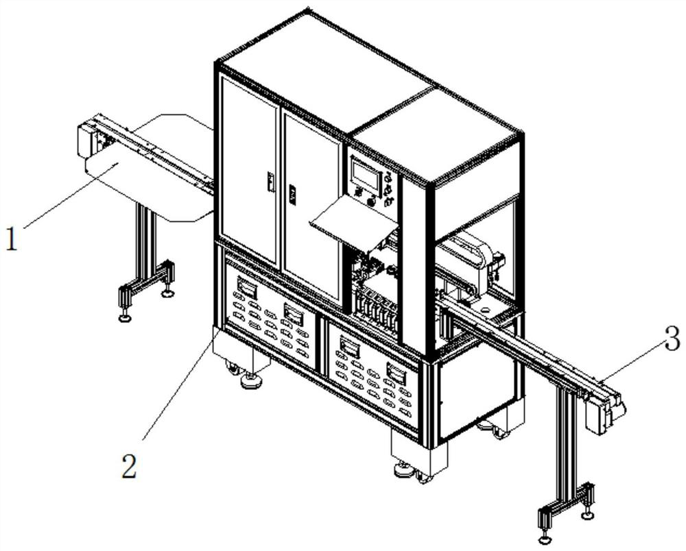
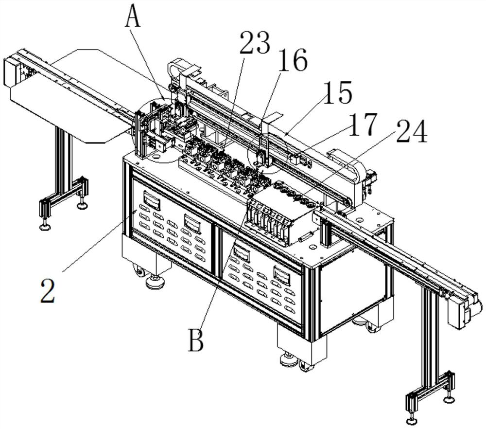
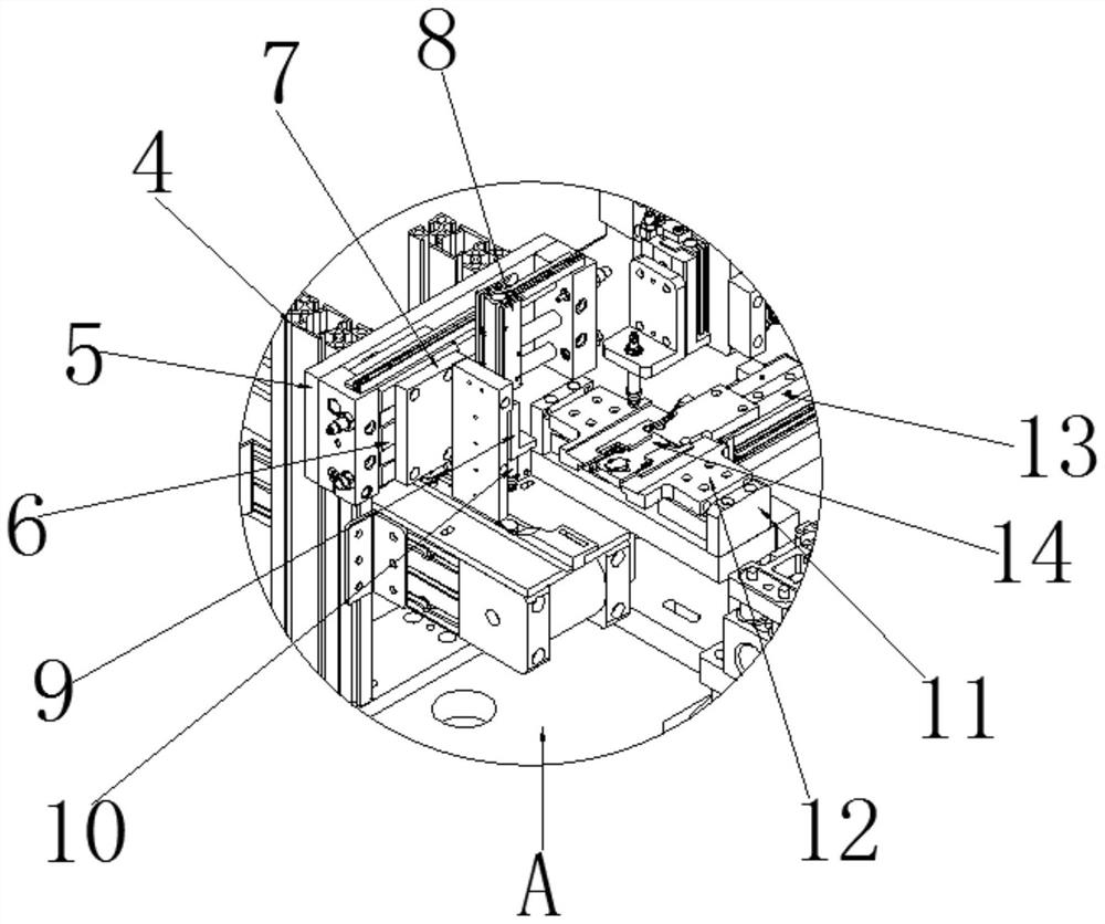
[0035] see Figure 1-7 As shown, an automatic testing device for the production of a vibration motor includes a feeding belt 1, a frame 2, a lowering belt 3, a translation frame 15, a test fixture 23 and an NG box 24, and one end of the frame 2 is equipped with a feeding belt 1 , the other end of the frame 2 is equipped with a blanking belt 3, the top of the frame 2 and is located at one end of the loading belt 1, and both sides are equipped with a bracket 4, and a horizontal frame 5 is installed on the top of the side of th...


PUM


Abstract

The invention discloses an automatic testing device for vibration motor production, which includes a feeding belt, a testing fixture and an NG box, a feeding belt is installed at one end of the frame, and a lowering belt is installed at the other end of the frame; the invention When the vibrating motor is placed on the limit slot of the motor positioning plate at one end of the test stand, the fourth air pressure rod starts to elongate and drives the bottom end of the fixed chuck connected to the connecting ear to move to both ends respectively, and then drives the fixed chuck to move in the limit position. Rotate in the groove, and at the same time fix the vibration motor in the motor positioning groove with the help of a spring, connect the positive and negative test fixtures with the vibration motor for performance testing, and test the waveform, speed, current and noise of the vibration motor in turn to achieve The vibration motor can complete the automatic test device during the performance test, which saves personnel and test stations, greatly improves the working efficiency of the vibration motor during the performance test, and eliminates the misjudgment phenomenon caused by manual pressing when the test is not in place. .

Description

technical field [0001] The invention relates to the field of vibration motor production equipment, in particular to an automatic testing device for vibration motor production. Background technique [0002] The vibration motor is a brushed DC motor. There is an eccentric wheel on the motor shaft. When the motor rotates, the center point of the eccentric wheel is not on the center of rotation of the motor, so that the motor is in a state of continuous loss of balance. Vibration is caused by inertia. After the production of the vibration motor is completed, its performance is tested, and the products that fail the performance test are eliminated. [0003] In the performance testing process of the existing vibration motors, multiple testing stations and personnel are required to manually press the vibration motors to perform performance testing operations. The equipment personnel occupy a lot of space. During the test, one hand needs to press the vibration motor, and the other h...

Claims


Application Information

Patent Timeline
Patent Type & Authority Patents(China)
IPC IPC(8): B07C5/344B07C5/36B07C5/38B07C5/02
CPCB07C5/02B07C5/344B07C5/361B07C5/38
Inventor 李伟德
Owner 阜南县特立电子有限公司
Learn More