
Yarn collecting plate type broken yarn detection device of warping machine

A technology for yarn breakage detection and yarn collecting board, which is applied to other manufacturing equipment/tools, textiles and papermaking, manufacturing tools, etc., can solve the problems of long output time of breakage signal, non-stop yarn breakage, affecting warping quality, etc.

Pending Publication Date: 2020-03-20
射阳县杰力纺织机械有限公司
View PDF0 Cites 1 Cited by
  • Summary
  • Abstract
  • Description
  • Claims
  • Application Information

AI Technical Summary

Problems solved by technology

[0002] Warping is an important process of weaving. The warping machine is an important process equipment for textiles. The broken yarn detection device is a necessary function in the warping process. At present, the yarn broken detection device equipped with the warping machine is installed on the creel. Some are on the front of the car, and some are formed between the front of the car and the bobbin after the yarn is formed into pieces, using falling sheet contact, infrared photoelectric, and photographic detection methods, all due to the relationship between the detection position and the performance of the detection method. As a result, yarn breakage sometimes does not stop automatically, many malfunctions, yarn friction affects tension, long end-break signal output time, and high cost, etc., which affect the quality of warping. It is urgent to develop a new type of warping yarn breakage detection device.

Method used

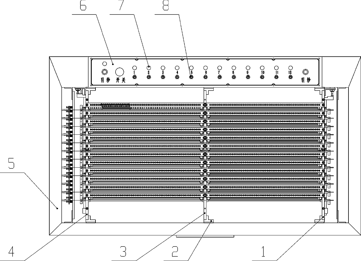
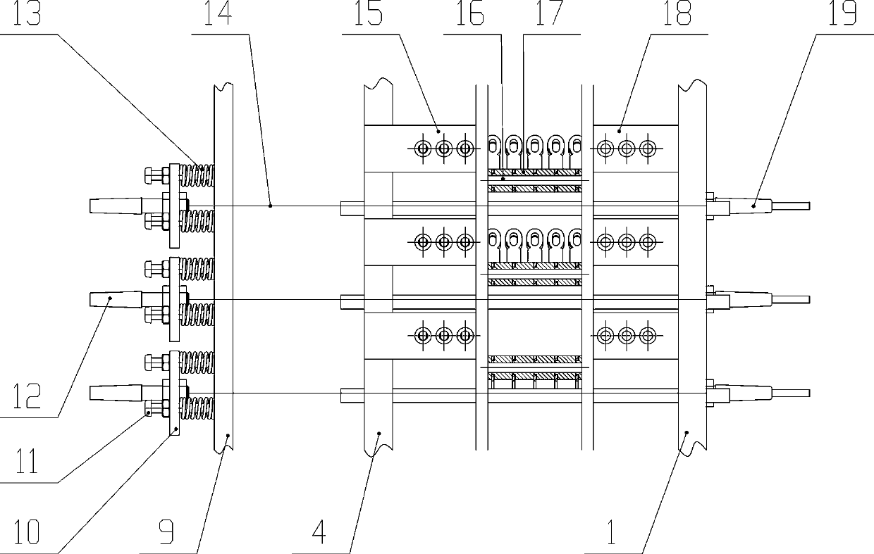
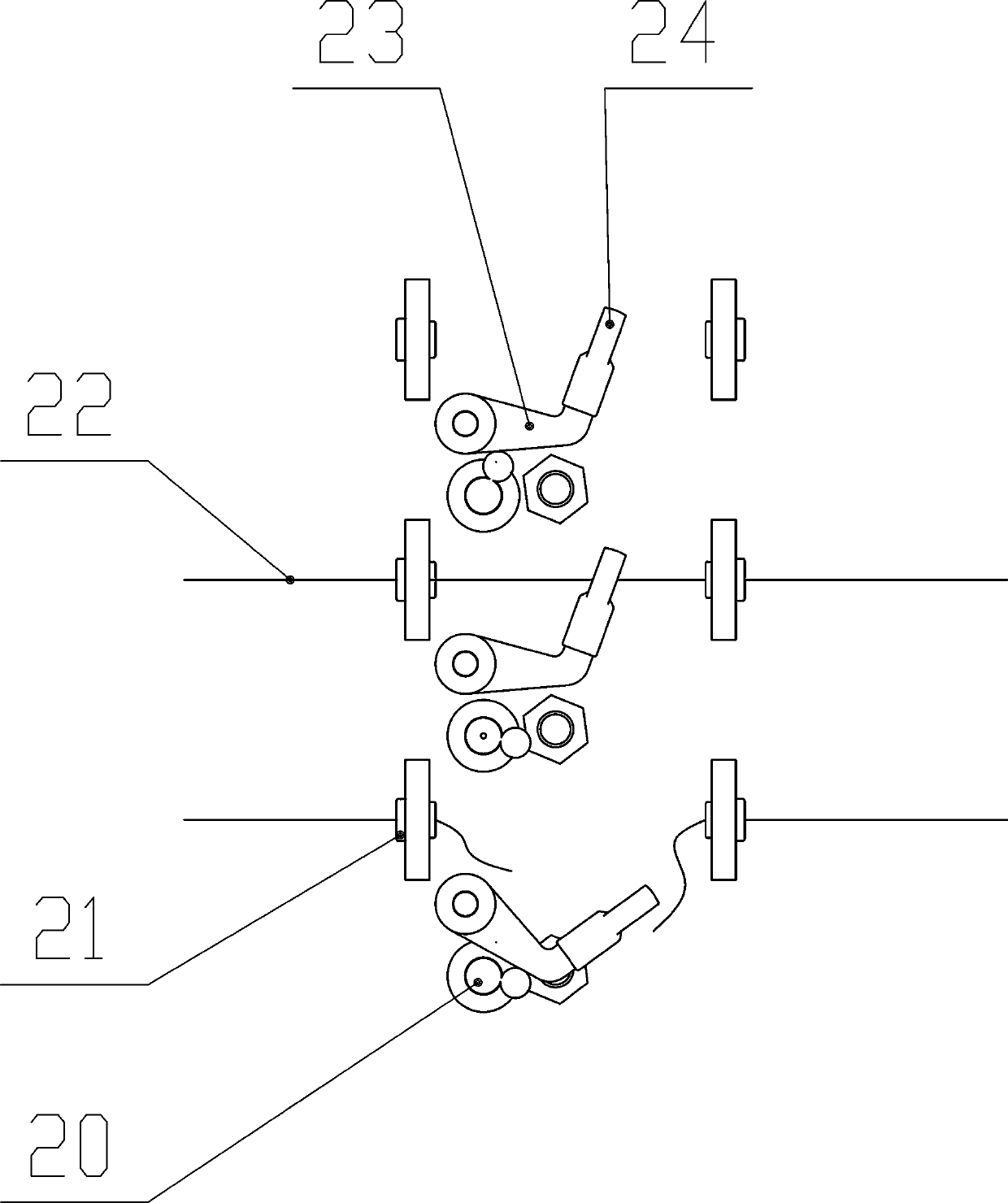

Image

  • Yarn collecting plate type broken yarn detection device of warping machine
  • Yarn collecting plate type broken yarn detection device of warping machine
  • Yarn collecting plate type broken yarn detection device of warping machine

Examples


Embodiment Construction

[0015] Depend on figure 1 , figure 2 and image 3 It can be seen that the warping machine yarn breakage detection device of the present invention is a warping machine filament collecting plate type yarn breakage detection device, which is characterized in that: the left vertical board 4, the middle vertical board 3 and the right vertical board are fixed in the frame 5 with corner seats 2 The two sides of 1, according to certain spacing up and down, are equipped with multi-layer front yarn guide plate 15 and rear yarn guide plate 18, are glued with porcelain eyes 21 on the front yarn guide plate 15 and rear yarn guide plate 18, in each layer front yarn guide plate 15 Between the back guide plate 18, there is a support bar 16, which passes through the left vertical plate 4, the neutral plate 3 and the right vertical plate 1 respectively, and many spacer sleeves 17 and yarn guide hooks 23 are arranged successively on the support bar 16. There is long porcelain eye 24 on the ho...


PUM


Abstract

The invention relates to a yarn collecting plate type broken yarn detection device of a warping machine. Angle seats are fixed on two sides of a left vertical plate, a middle vertical plate and a right vertical plate in a frame; multiple layers of front yarn guiding plates and rear yarn guiding plates are arranged up and down at certain intervals; a support rod is arranged between every two layersof plates; a plurality of spacers and yarn guiding hooks are sequentially connected on each support rod in series; a hook supporting rod is arranged below each yarn guiding hook; a pair of photoelectric emitting heads and photoelectric receiving heads are respectively arranged on the front upper side of the left vertical plate and the front upper side of the right vertical plate through which each hook supporting rod passes; during warping, the yarn guiding hooks are lifted under the tension of yarns, light beams emitted by the photoelectric emitting heads irradiate on the photoelectric receiving heads, when the yarns are broken, the yarn guiding hooks fall down by means of dead weight, the light beams are blocked, a yarn breaking signal is sent out by the photoelectric receiving heads, when the yarns are drawn, the hook supporting rods rotate under the action of external force, the yarn guiding hooks are completely supported, needle threading and yarn drawing are facilitated, brokenhead detection and a wire collecting plate are integrated, and the device is compact in structure, sensitive, reliable, convenient to operate, economical, practical and novel in design.

Description

technical field [0001] The invention relates to the field of textile machinery, in particular to a yarn break detection device for warping equipment. Background technique [0002] Warping is an important process of weaving. The warping machine is an important process equipment for textiles. The broken yarn detection device is a necessary function in the warping process. At present, the yarn broken detection device equipped with the warping machine is installed on the creel. Some are on the front of the car, and some are formed between the front of the car and the bobbin after the yarn is formed into pieces, using falling sheet contact, infrared photoelectric, and photographic detection methods, all due to the relationship between the detection position and the performance of the detection method. As a result, yarn breakage sometimes does not stop automatically, many malfunctions, yarn friction affects tension, long end-break signal output time, and high cost, etc., which aff...

Claims


Application Information

Patent Timeline
IPC IPC(8): D02H13/08
CPCD02H13/08
Inventor 黄翠玉胡卫红黄以利
Owner 射阳县杰力纺织机械有限公司
Learn More