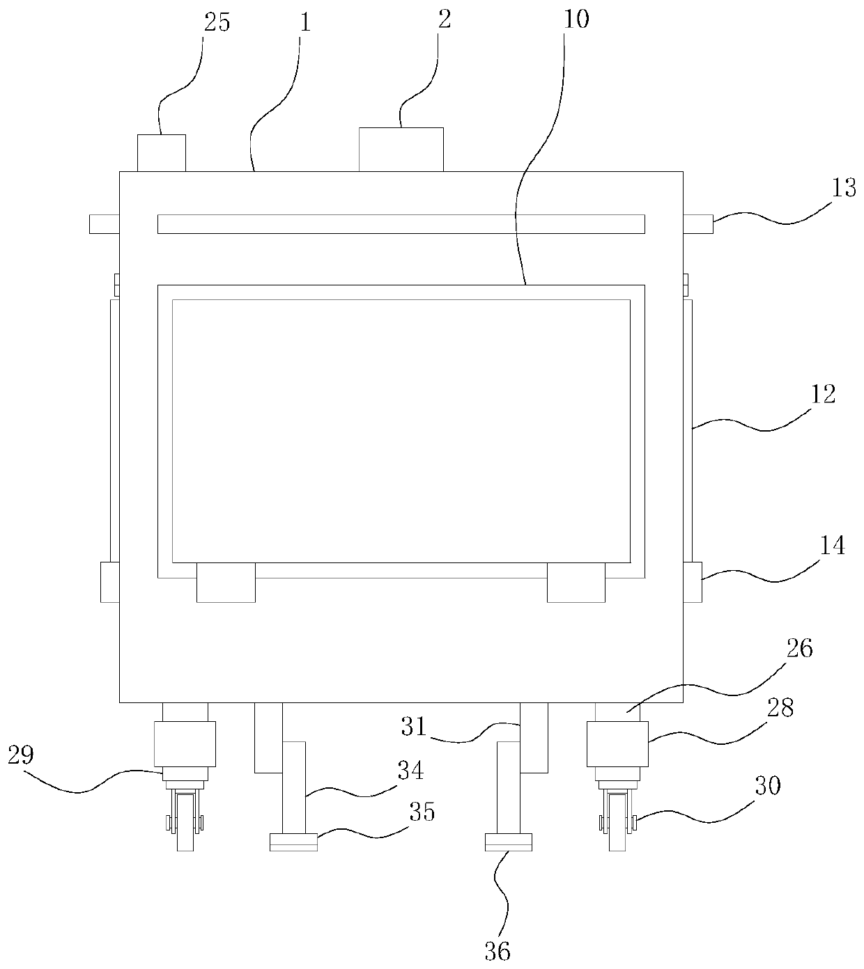
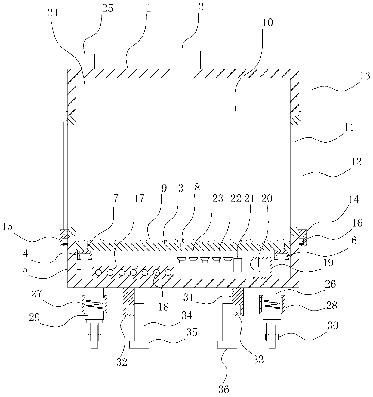
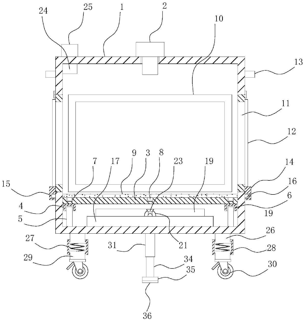
Observation device for culture in vitro of KM mouse embryos
A technology of in vitro culture and observation device, which is applied in the cultivation device of tissue cells/viruses, biochemical cleaning device, enzymology/microbiology device, etc., which can solve the problem of not being able to observe KM mice in all aspects, and the inconvenient disassembly of the placement plate. and other problems to achieve the effect of ensuring the production temperature
- Summary
- Abstract
- Description
- Claims
- Application Information
AI Technical Summary
Problems solved by technology
Method used
Image
Examples
Embodiment 1
[0024] refer to Figure 1-3 , a KM mouse embryo in vitro culture observation device, comprising an observation box 1, the observation mirror 2 is installed on the top of the observation box 1, the four corners of the bottom of the observation box 1 are welded with the first support rod 5, the first support rod 5 The top end is clamped with a fixed block 4, and the bottom end of the fixed block 4 is provided with a first slot 6 that matches the first support rod 5. The top of the fixed block 4 is welded with a placement plate 3, and the top of the placement plate 3 is evenly opened. There is a second card slot 7, the first card block 8 is connected to the inside of the second card slot 7, the top of the first card block 8 is bonded with a sterilizing protection pad 9, the observation box 1, the placement plate 3, the fixed block 4, The cooperative setting between the first support rod 5 and the first draw-in groove 6 can facilitate the removal of the placement plate 3, thereby ...
Embodiment 2
[0028] refer to Figure 1-3As another preferred embodiment of the present invention, the difference from Embodiment 1 is that the support mechanism includes first support legs 26 welded to the four corners of the bottom end of the viewing box 1, and shock absorbing springs are welded to the bottom ends of the first support legs 26 27. One end of the damping spring 27 is welded with a second support leg 29, and the bottom end of the second support leg 29 is welded with a universal wheel 30. A connecting mechanism is installed between the first support leg 26 and the second support leg 29, and the connection The mechanism includes a sleeve rod 28 slidably socketed under the first support leg 26. The middle part of the sleeve rod 28 is provided with a chute matching with the first support leg 26. The top end of the second support leg 29 is slidably connected to the sleeve rod 28. In the chute in the middle, the damping spring 27 between the first support leg 26 and the second sup...
Embodiment 3
[0030] refer to Figure 1-3 , as another preferred embodiment of the present invention, the difference from Embodiment 1 is that the fixing mechanism includes a fixing rod 31 symmetrically welded in the middle of the bottom end of the viewing box 1, and a second support rod is connected below the fixing rod 31 through a rotating mechanism 34. The rotating mechanism includes a rotating groove 32 provided below the fixed rod 31, a connecting shaft 33 is rotatably connected in the rotating groove 32, and a second supporting rod 34 is welded on one end of the connecting shaft 33, and the bottom end of the second supporting rod 34 is welded There is a friction plate 35, and the bottom end of the friction plate 35 is bonded with an anti-slip pad 36, and the cooperation between the fixed rod 31, the rotating groove 32, the connecting shaft 33, the second support rod 34 and the friction plate 35 is arranged to facilitate fixing the observation box 1. To avoid movement of the observati...
PUM
 Abstract
Description
Claims
Application Information
 - R&D
- Intellectual Property
- Life Sciences
- Materials
- Tech Scout
- Unparalleled Data Quality
- Higher Quality Content
- 60% Fewer Hallucinations
Browse by: Latest US Patents, China's latest patents, Technical Efficacy Thesaurus, Application Domain, Technology Topic, Popular Technical Reports.
© 2025 PatSnap. All rights reserved.Legal|Privacy policy|Modern Slavery Act Transparency Statement|Sitemap|About US| Contact US: help@patsnap.com


