
Charging pile, vehicle charging method, device, electric vehicle and charging system

A technology of electric vehicles and charging methods, which is applied in the field of vehicles, can solve the problems of high vehicle configuration requirements, complex controller software, and inapplicability, and achieve the effects of simplifying operation steps, facilitating charging time, and realizing off-peak power consumption

Inactive Publication Date: 2020-03-20
BEIQI FOTON MOTOR CO LTD
View PDF13 Cites 0 Cited by
  • Summary
  • Abstract
  • Description
  • Claims
  • Application Information

AI Technical Summary

Problems solved by technology

If a large number of electric vehicles are charged during the peak load period, it will further aggravate the peak-valley load difference of the power grid and increase the burden on the power system
In addition, since the electricity price during the peak load period (for example: 8:00-11:00, 18:00-23:00) is higher than the electricity price during the low load period (for example: 23:00-7:00), therefore, For users, most of them charge electric vehicles during the peak load period, resulting in an increase in the electricity cost of using electric vehicles
[0003] At present, many high-end passenger cars (such as Tesla, etc.) have satisfied the user's scheduled charging function by configuring a controller on the car that can set the time and self-time. However, this method requires high configuration of the vehicle and costs a lot. High, and the controller software is complex, and the development and testing cycle is long
It is not suitable for commercial electric vehicles, especially logistics transport vehicles, which require low vehicle cost

Method used


Image

  • Charging pile, vehicle charging method, device, electric vehicle and charging system
  • Charging pile, vehicle charging method, device, electric vehicle and charging system
  • Charging pile, vehicle charging method, device, electric vehicle and charging system

Examples


Embodiment approach

[0082] A possible implementation manner: the charging pile includes a timer. When the charging start time input by the user is a specific time, the timer can use the moment when the charging start time is set as the starting point, and subtract this time. The moment is the moment when the charging pile starts to charge the electric vehicle. For example, assuming that the charging start time input by the user is 150 minutes, the timer starts from the moment when the user enters the charging start time, and subtracts the above 150 minutes until the timer ends, that is, it is determined that the current time has reached the charging start time input by the user .

[0083] Another possible implementation: the charging pile includes a timer. When the charging start time input by the user is a specific time, the timer can start timing at the moment when the charging start time is set until the timer When the recorded time reaches the charging start time, the moment when the chargin...


PUM


Abstract

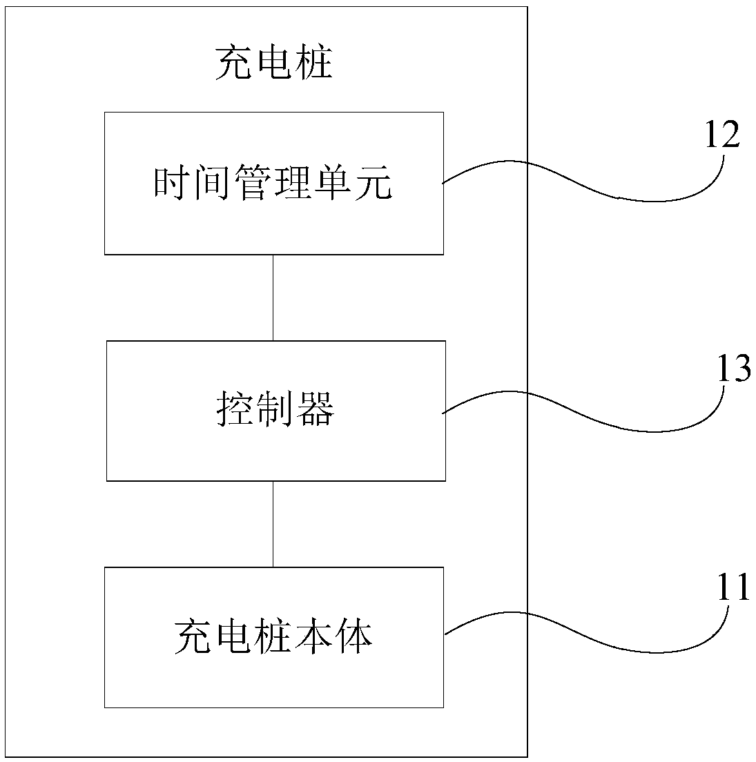
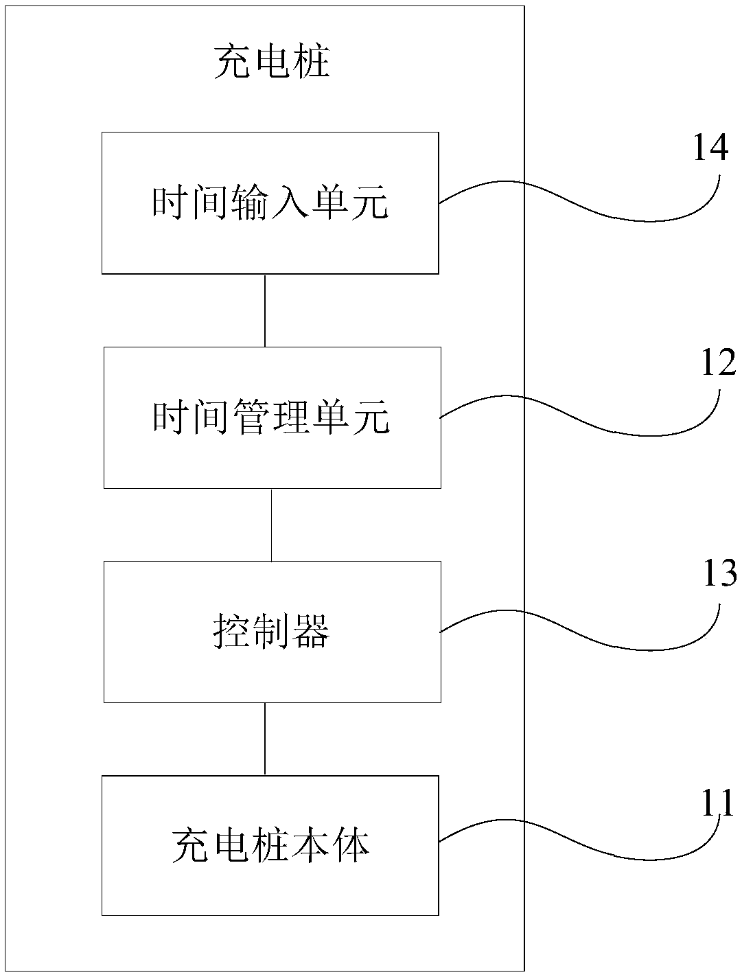
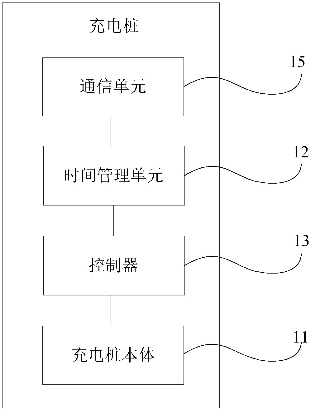
The invention relates to a charging pile, a vehicle charging method, a device, an electric vehicle and a charging system. The charging pile comprises a charging pile body, a time management unit and acontroller, wherein the time management unit and the controller are arranged on the charging pile body. The time management unit is connected with the controller, the time management unit is used forobtaining charging starting time input by a user and sending a control signal to the controller when the charging starting time is up, and the controller controls the charging pile body to start to charge the electric vehicle when receiving the control signal. Namely, the charging pile receives the charging starting time in advance and starts to charge the electric vehicle when the charging starting time is up, so that appointment charging can be performed through the charging pile, off-peak power utilization is realized, the power utilization cost of the electric vehicle is saved, and a usercan reasonably arrange the charging time conveniently. And a controller with a timing function or a timing function does not need to be configured in the electric vehicle, so that the electric vehicle is simple to configure, and the cost is reduced.

Description

technical field [0001] The present disclosure relates to the technical field of vehicles, and in particular, to a charging pile, a vehicle charging method and device, an electric vehicle and a charging system. Background technique [0002] With everyone's emphasis on energy conservation and environmental protection and the vigorous promotion of national policies, electric vehicles have developed rapidly. Since electric vehicles use the electric energy in the power battery as the power source, charging is an unavoidable key behavior. More and more electric vehicles are connected to the grid for charging on a large scale, which will affect the operation and planning of the entire grid system. If a large number of electric vehicles are charged during the peak load period, it will further aggravate the peak-valley load difference of the power grid and increase the burden on the power system. In addition, since the electricity price during the peak load period (for example: 8:0...

Claims


Application Information

Patent Timeline
IPC IPC(8): B60L53/31B60L53/60
CPCY02T10/70Y02T10/7072Y02T90/12
Inventor 程琰
Owner BEIQI FOTON MOTOR CO LTD
Learn More