
Lithium battery cap

A technology for lithium batteries and caps, which is applied to battery boxes/coats, battery pack components, circuits, etc., and can solve problems such as poor quality of sealing rings, shedding, and increased battery manufacturing costs

Active Publication Date: 2020-03-17
ANHUI FEIKAI ELECTRONICS TECH CO LTD
View PDF12 Cites 0 Cited by
  • Summary
  • Abstract
  • Description
  • Claims
  • Application Information

AI Technical Summary

Problems solved by technology

[0002] In the battery manufacturing process, the connection between the battery body and the small aluminum sheet of the combined cap is mostly welding, which is inconvenient to operate, reduces efficiency, and virtually increases the manufacturing cost of the battery;
[0003] The Chinese patent with the application number of prior art 201810803597.1 discloses a lithium battery cap, which is characterized in that it includes a cover, a sealing ring, a top cover, a long elastic piece, a short elastic piece and an aluminum piece. Cylindrical, the cover is tightly sleeved on the sealing ring, the upper end of the sealing ring is sleeved on the top cover, and the middle end of the sealing ring is sleeved on the elastic long piece and the elastic On the short piece, the elastic short piece is located below the elastic long piece, and the lower end of the sealing ring is sleeved on the aluminum piece, which solves the problem that the poor quality of the traditional sealing ring will affect the sealing effect, not only easy to leak, but also cause The small aluminum sheet deforms or falls off directly, which may easily cause positive and negative short circuits.

Method used


Image

  • Lithium battery cap
  • Lithium battery cap

Examples


Embodiment Construction

[0015] In order to make the technical means, creative features, goals and effects achieved by the present invention easy to understand, the present invention will be further described below in conjunction with specific embodiments.

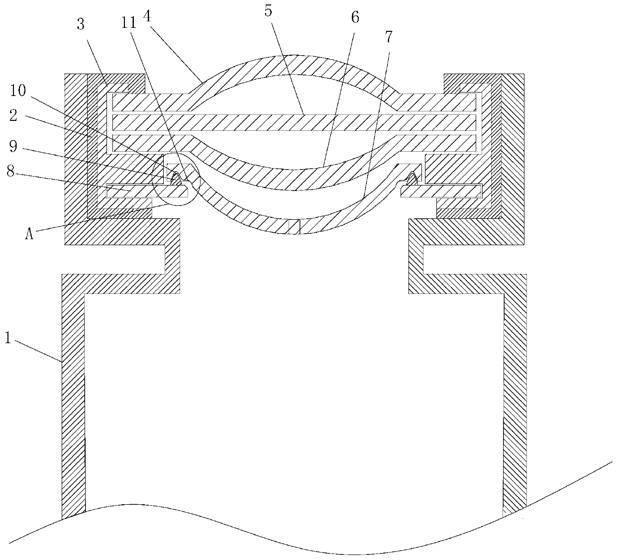
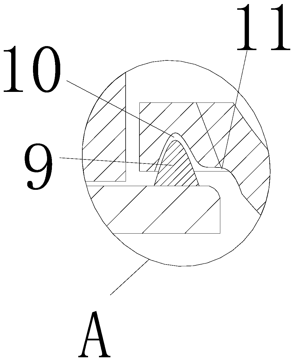
[0016] Such as Figure 1-2 As shown, a lithium battery cap includes a battery body 1, and a combined cap is embedded on the top thereof. The combined cap includes a cover body 2, a sealing ring 3, a top cover 4, a bottom cover 5, a long elastic piece 6, a short elastic piece 7 and The aluminum sheet 8, the top of the aluminum sheet 8 is located between the sealing rings 3 and is located at a symmetrical position in contact with the elastic short piece 7, and a bump 9 with a tapered cross section is provided, and the elastic short piece 7 is located at the position of the bump 9 and has an adapter groove 10 , that is, when assembling the battery body and the combination cap, pass the guide piece of the battery body through the fitting groove, and t...


PUM


Abstract

The invention discloses a lithium battery cap. The lithium battery cap comprises a battery body, a combined cap is embedded in the top of the battery body, and the combined cap comprises a cap body, sealing rings, a top cap, a bottom cap, an elastic long piece, an elastic short piece and an aluminum piece. Protruding blocks with conical sections are arranged at the positions, located between the sealing rings and symmetrical to the positions contacted with the elastic short piece, of the top of the aluminum piece, and adaptive grooves are formed at the positions, located on the protruding blocks, of the elastic short piece, namely when the battery body and the combined cap are assembled, the guide pieces of the battery body penetrate through the adaptive grooves. According to the invention, the guide sheets can be bent into the hook shapes under the action of the adaptive grooves and the protruding blocks to hook the protruding blocks, and then the battery body and the combined cap areassembled, the battery body abuts against the elastic short piece to enable the adaptive grooves of the elastic short piece to be far away from each other so as to clamp the guide pieces and preventthe guide pieces from sliding off, during disassembly, the combined cover cap is taken out, the elastic short piece is reset, then the guide pieces are not be clamped and are pulled out, so that the operation is convenient and rapid, and the process is simple and practical.

Description

technical field [0001] The invention relates to the technical field of electric battery accessories, in particular to a lithium battery cap. Background technique [0002] In the battery manufacturing process, the connection between the battery body and the small aluminum sheet of the combined cap is mostly welding, which is inconvenient to operate, reduces efficiency, and virtually increases the manufacturing cost of the battery; [0003] The Chinese patent with the application number of prior art 201810803597.1 discloses a lithium battery cap, which is characterized in that it includes a cover, a sealing ring, a top cover, a long elastic piece, a short elastic piece and an aluminum piece. Cylindrical, the cover is tightly sleeved on the sealing ring, the upper end of the sealing ring is sleeved on the top cover, and the middle end of the sealing ring is sleeved on the elastic long piece and the elastic On the short piece, the elastic short piece is located below the elasti...

Claims


Application Information

Patent Timeline
IPC IPC(8): H01M2/04H01M2/08
CPCH01M50/148H01M50/183Y02E60/10
Inventor 陈凯
Owner ANHUI FEIKAI ELECTRONICS TECH CO LTD
Learn More