
Unmanned rolling machine positioning method

A positioning method and unmanned driving technology, which can be used in measuring devices, instruments, surveying and mapping and navigation, etc., can solve the problems of high vibration intensity, harsh working environment of roller compactors, affecting positioning accuracy, etc. Effect

Inactive Publication Date: 2020-03-17
TIANJIN UNIV
View PDF8 Cites 2 Cited by
  • Summary
  • Abstract
  • Description
  • Claims
  • Application Information

AI Technical Summary

Problems solved by technology

Due to the harsh working conditions of the rolling machine (high-intensity vibration, dust, humidity), the existing positioning method has the following problems: the existing solution uses GPS (Global Positioning System) positioning, and the effect is directly related to the signal strength of the GPS satellite. Changes, GPS signal reception will be affected, which will lead to unstable positioning
In addition, the GPS (Global Positioning System) positioning method is often used in conjunction with the IMU (Inertial Measurement Unit). Due to the harsh working environment and high vibration intensity of the rolling machine, the IMU based on inertial measurement will be interfered, which will affect the positioning accuracy.

Method used


Image

  • Unmanned rolling machine positioning method
  • Unmanned rolling machine positioning method
  • Unmanned rolling machine positioning method

Examples


Embodiment Construction

[0029] The present invention will be further described in detail below in conjunction with the accompanying drawings and through specific embodiments. The following embodiments are only descriptive, not restrictive, and cannot limit the protection scope of the present invention.

[0030] A positioning method for an unmanned rolling machine, the specific steps are as follows:

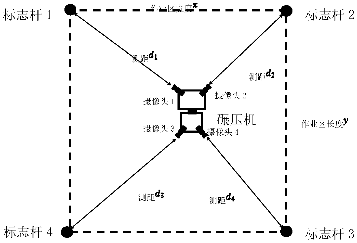
[0031] (1) Arranging the operation area, specifically to determine the operation area of ​​the roller compactor, the operation area is a rectangular area, and a signpost is installed at the four corners of the operation area; an image acquisition device is respectively installed at the four corners of the body of the roller compactor, and the image acquisition The shooting direction of the device corresponds to the sign poles at the four corners of the area;

[0032] The working area is positioned as a grid map, and each coordinate point is set with a unique coordinate (x, y).

[0033] The sign post has...


PUM


Abstract

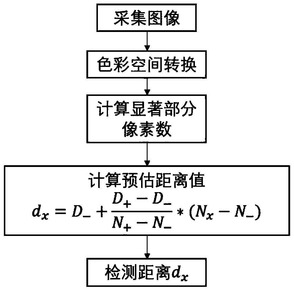
The invention relates to an unmanned rolling machine positioning method. The method is characterized by comprising specific steps of (1) arranging an operation area; (2) respectively acquiring imagesby an image acquisition device to perform visual ranging; and (3) calculating position coordinates of a rolling machine according to a distance between the rolling machine and a plurality of marker posts, and positioning the actual position of the rolling machine in the operation area. The method is scientific and reasonable in design, and does not depend on GPS and IMU schemes in the prior art, so the GPS and IMU are prevented from being affected due to poor signals and vibration of the rolling machine, and positioning robustness is improved. The method is advantaged in that the method can coexist with a positioning method based on the GPS and the IMU, not only can a remarkable target be provided for positioning, but further communication service can be provided for the rolling machine and a command center in a rolling machine operation area.

Description

technical field [0001] The invention belongs to the field of unmanned driving control, in particular to a positioning method for an unmanned rolling machine. Background technique [0002] The construction conditions of hydropower dam construction are very difficult, and the work intensity is high. During the compaction operation, problems such as irregular distance and speeding are prone to occur. Once a quality problem occurs during the compaction process, it takes time and effort to remedy the problem afterwards. [0003] In recent years, with the development of unmanned driving technology and artificial intelligence technology, unmanned rolling machines have gradually attracted attention. The positioning of the rolling machine is an important technical link of the unmanned rolling machine, which directly determines the scheduling and operation quality of the unmanned rolling machine. At present, the positioning of the rolling machine is mainly based on GPS (Global Posit...

Claims


Application Information

Patent Timeline
Patent Type & Authority Applications(China)
IPC IPC(8): G01C21/20G01C21/00G01C3/00
CPCG01C3/00G01C21/005G01C21/20
Inventor 谢辉周扬孙一铭
Owner TIANJIN UNIV
Learn More