
Predetermined time projection synchronization method of delay memristor neural network with unknown disturbance resistance

A predetermined time, neural network technology, applied in instruments, adaptive control, control/regulation systems, etc., can solve problems such as difficulty in finding the direct relationship between system gain and upper limit of convergence time, interference, etc.

Active Publication Date: 2020-03-13
FUZHOU UNIV
View PDF5 Cites 8 Cited by
  • Summary
  • Abstract
  • Description
  • Claims
  • Application Information

AI Technical Summary

Problems solved by technology

When applying constant-time stability to a control or observation task, it is difficult to find a direct relationship between the system gain and the upper bound on the convergence time
Moreover, in practical applications, it is inevitable to be subject to external unknown interference

Method used

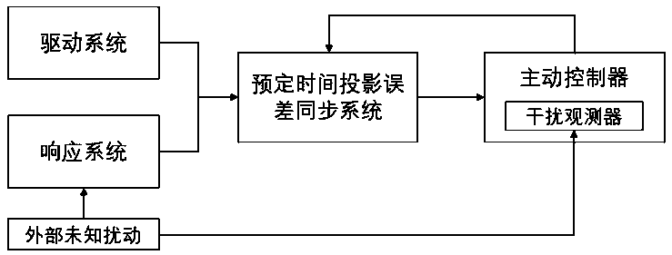

Image

  • Predetermined time projection synchronization method of delay memristor neural network with unknown disturbance resistance
  • Predetermined time projection synchronization method of delay memristor neural network with unknown disturbance resistance
  • Predetermined time projection synchronization method of delay memristor neural network with unknown disturbance resistance

Examples


specific Embodiment 1

[0148] The state equation of the driving system is:

[0149]

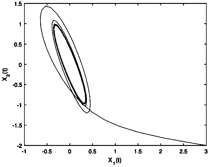
[0150] Among them, the driving system is a 2-dimensional chaotic system, x i The initial state of (t) is set to [3,-2] T . figure 2 Expressed as the chaotic behavior of the system.

[0151] The state equation of the response system is:

[0152]

[0153] Among them, the response system is a 2-dimensional chaotic system, y i The initial state of (t) is set to [-1,1.5] T . Here are the settings for some known parameters:

[0154]

[0155]

[0156]

[0157]

[0158] The projection error of the drive-response system is set as:

[0159] e i (t)=y i (t)-x i (t); (23)

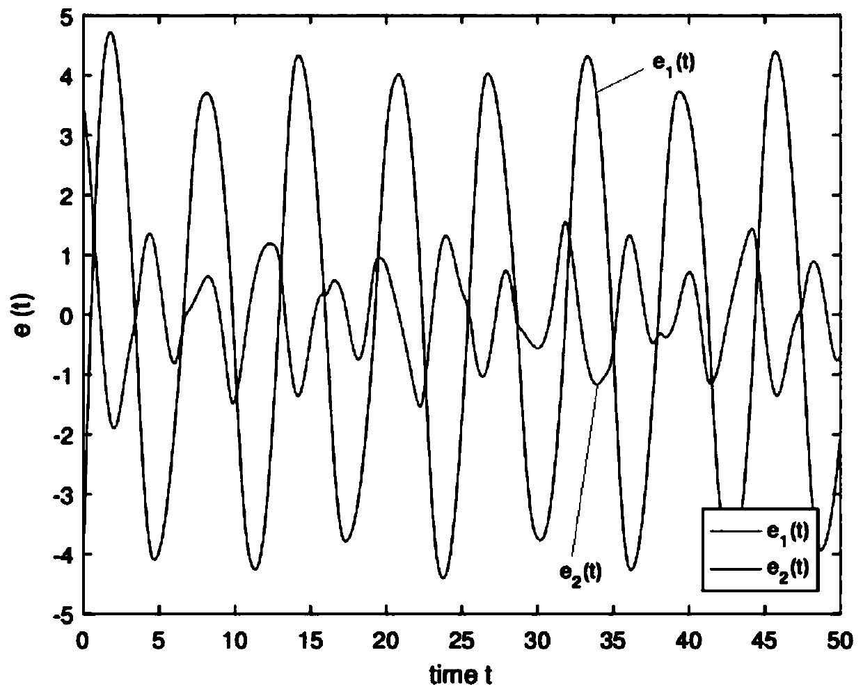
[0160] image 3 Expressed as the response curve of the projected synchronization error in the absence of active controller input.

[0161] (1-1) Assuming that there is no unknown disturbance outside, then there is no need to use the disturbance observer to compensate the error effect caused by the unknown disturbance. At thi...

specific Embodiment 2

[0177] drive systemx i The initial state of (t) is set to [3,-0.5] T , the response system y i The initial state of (t) is set to [-2,4] T . Here are the settings for some known parameters:

[0178]

[0179]

[0180] ω(t)=sint, τ(t)=1, q=2,b 1 =0.2,b2 =0.1,c 1 = 1,c 2 =1.5, w(0)=-0.5,

[0181]

[0182] (2-1) Setting T c1 =T c2 =0.5, according to the satisfaction condition of the gain control parameter in step 5, wherein the gain control parameter is set to k 1 = 3,k 2 = 1,w 1 =11,w 2 =9, h 11 = 2.2, h 12 = 1.4, h 21 = 1.4, h 22 = 2.5. The control parameters are shown in formula (29), and the simulation experiment is carried out. Figure 6 (a) shows the synchronous error response curve projected at a predetermined time under the input of active controllers (14) and (15). exist Figure 6 In (a), the system converges to zero at 0.3759s.

[0183] (2-2) Setting T c1 =T c2 = 1.0, according to the satisfaction condition of the gain control parameter ...


PUM


Abstract

The invention relates to a predetermined time projection synchronization method for a delay memristor neural network with unknown disturbance resistance, and the method comprises the following steps:S1, building a drive system and a response system based on the delay memristor neural network; S2, establishing a preset time projection synchronization error system according to the driving system and the response system established in the step S1; S3, designing a disturbance observer for estimating external unknown disturbance, and compensating error influence of the unknown disturbance on system synchronization; and S4, designing different active controllers according to different conditions so as to carry out balance control on the projection synchronization error system in the preset time. According to the invention, the preset time projection synchronization of the delay memristor neural network with unknown disturbance resistance can be realized.

Description

technical field [0001] The invention relates to the technical field of automatic control, in particular to a predetermined time projection synchronization method of a delay memristive neural network capable of resisting unknown disturbances. Background technique [0002] Finite-time stability refers to the stability of the state trajectory relative to a certain time interval after the system is subjected to an initial disturbance. The stable establishment time of the system with finite-time stability is closely related to the initial state, but in some practical systems, such as robot operating systems, vehicle monitoring systems, power systems, and spacecraft attitude dynamic systems, it is difficult to obtain the initial state of the system. state. The lack of these initial information directly leads to the inability to estimate the stable establishment time of the system. Therefore, in 2012, Polyakov proposed a special kind of finite-time stability, which he called fixe...

Claims


Application Information

Patent Timeline
IPC IPC(8): G05B13/04
CPCG05B13/042
Inventor 林立雄吴培鑫何炳蔚张立伟陈彦杰
Owner FUZHOU UNIV
Learn More