Quick switching module device for automobile gauge tool
A fast switching and tooling technology, applied in the direction of measuring devices, mechanical devices, mechanical measuring devices, etc., can solve the problems of reduced efficiency, long installation time, poor rigidity and stability of the base, etc. The effect of improving installation efficiency and increasing stability
- Summary
- Abstract
- Description
- Claims
- Application Information
AI Technical Summary
Problems solved by technology
Method used
Image
Examples
Embodiment 1
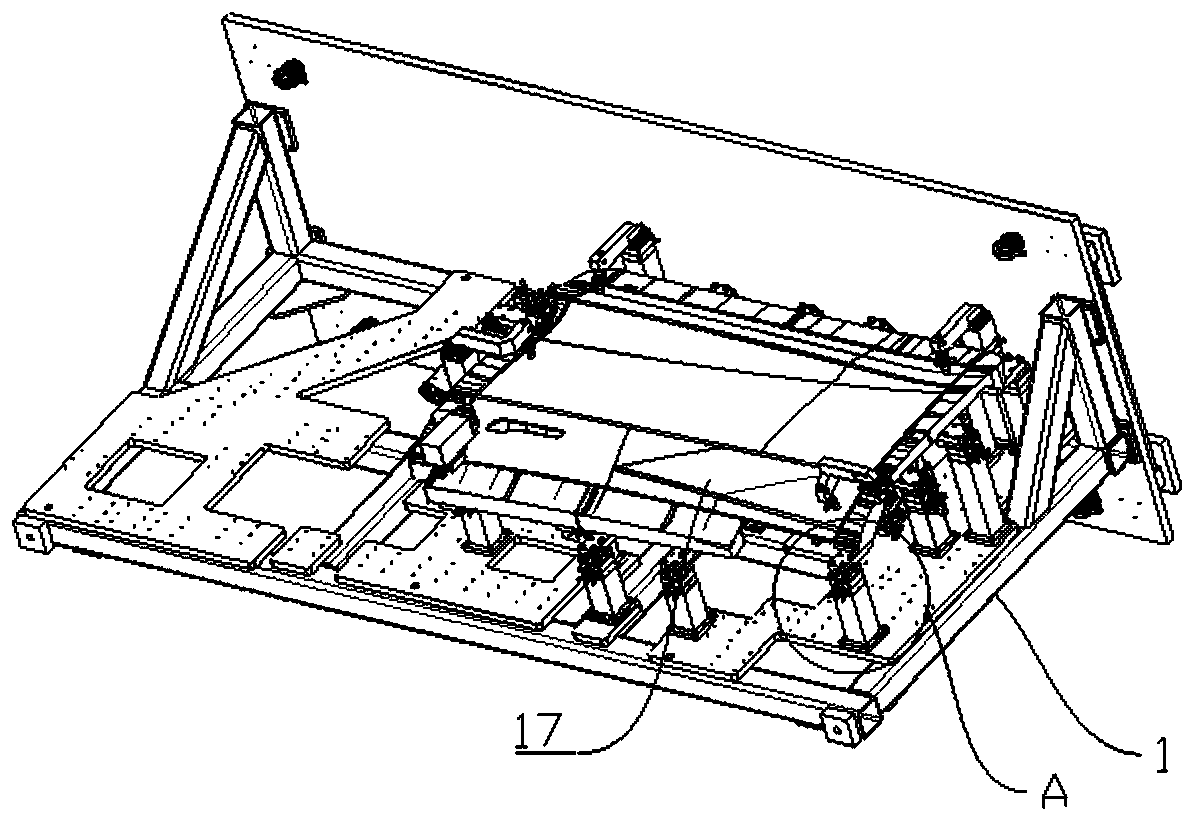
[0047] Such as Figure 3-Figure 18 As shown, this embodiment provides a quick switching module device for automobile inspection tooling, including a raised seat 2 arranged on the base plate 1, a disassembly module mounting seat installed on the raised seat 2, and a disassembly module mounting seat arranged on the disassembly module mounting seat. Seat 3; the demolition module mounting seat includes a lower base 4 and an upper base 5, the lower base 4 is fixedly installed on the upper end of the raised seat 2, the upper base 5 is fixedly connected with the dismounting seat 3, and anti-rotation is provided before the lower base 4 and the upper base 5 Pin 6, specifically, the anti-rotation pin 6 is arranged at the bottom of the upper base 5, and the upper end of the lower base 4 is provided with a pin hole 7, and the anti-rotation pin 6 is located in the pin hole 7, and the lower base 4 includes the lower base body 4.1 and the lower base body 4.1. The base body 4.1 rotates the ro...
Embodiment 2
[0052] This embodiment is optimized and defined on the basis of the above-mentioned embodiment 1.
[0053] In order to guide the rotation direction of the rotation sleeve 8, a guiding structure for guiding the rotation direction of the rotation sleeve 8 is provided between the rotation sleeve 8 and the lower base body 4.1. The guide pin 13 on the body 4.1, the guide pin 13 is slidingly matched with the guide groove 12, in order to ensure the horizontal rotation of the rotating sleeve 8, the guide groove 12 is horizontally arranged along the outer wall of the rotating sleeve 8. Specifically, two guide grooves 12 are symmetrically provided along the outer wall of the rotating sleeve 8 , and two guide pins 13 slidingly fitted with the guide grooves 12 are also provided.
Embodiment 3
[0055] This embodiment is optimized and defined on the basis of the above-mentioned embodiment 1.
[0056] The locking groove 11 is an inverted L-shaped locking groove 11. The upper end of the inverted L-shaped locking groove 11 is the locking end 11.1, and the lower end is the opening end 11.2. The locking pin 9 is located at the locking end 11.1 to realize the locking of the upper base 5 and the lower base 4. The pin 9 is located at the open end 11.2, and the upper base 5 and the lower base 4 are not locked, so that the upper base 5 and the lower base 4 can be easily separated.
[0057] Specifically, three locking pins 9 are evenly arranged along the axis of the rotating sleeve 8 , and three inverted L-shaped locking grooves 11 are evenly arranged along the outer wall of the positioning column 10 .
PUM
 Abstract
Description
Claims
Application Information
 - R&D
- Intellectual Property
- Life Sciences
- Materials
- Tech Scout
- Unparalleled Data Quality
- Higher Quality Content
- 60% Fewer Hallucinations
Browse by: Latest US Patents, China's latest patents, Technical Efficacy Thesaurus, Application Domain, Technology Topic, Popular Technical Reports.
© 2025 PatSnap. All rights reserved.Legal|Privacy policy|Modern Slavery Act Transparency Statement|Sitemap|About US| Contact US: help@patsnap.com


