Cannonball disintegration line and disintegration method thereof

A projectile and projectile technology, which is applied to the shell decomposition line and its decomposition field, can solve the problems of general work efficiency, insufficient safety performance, and cumbersome decomposition process.

Pending Publication Date: 2020-03-13
ARMY ENG UNIV OF PLA +1
View PDF10 Cites 3 Cited by
  • Summary
  • Abstract
  • Description
  • Claims
  • Application Information

AI Technical Summary

Problems solved by technology

[0002] Shell disintegration is the disassembly and decomposition of scrapped shells, which is an essential process for subsequent classification and processing of shell materials; for example, Chinese patent application number: 201610242363.5 discloses a fixed-mounted shell decomposition machine, including a bracket, a fixed head and a sliding machine Tail; the fixed head is arranged on the bracket, the fixed head includes a shaft sleeve arranged in the head casing, and a pulley sleeve is arranged between the shaft sleeve and the head casing so that the shaft sleeve can Axial movement in the nose shell, the front end of the bushing is provided with a clamping elastic mold, the clamping elastic mold is sleeved on the nose shell through a fixed sleeve, and the rear end of the nose shell is set There is a decomposing driving device, the decomposing driving device is used to drive the shaft sleeve to move axially so as to compress the clamping mold to make it shrink radially; the sliding tail is set on the bracket through a guide rail and A tail drive mechanism for driving the sliding tail is provided, and the sliding tail includes an engaging mechanism for clamping the tail of the gun barrel; the whole process is simple in structure, but its safety performance is not high enough, and its working efficiency is average , in addition, the existing cannonball decomposition process generally uses the cannonball disintegration machine and manual cooperation to complete the decomposition, and each step requires manual participation, the decomposition process is cumbersome, and the safety performance is insufficient

Method used


Image

  • Cannonball disintegration line and disintegration method thereof
  • Cannonball disintegration line and disintegration method thereof
  • Cannonball disintegration line and disintegration method thereof

Examples


Embodiment 1

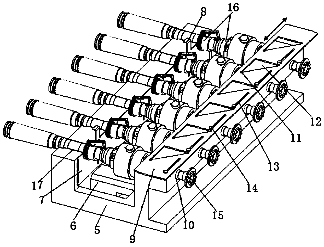
[0058] Such as figure 1 As shown, the shell decomposing line of the present invention adopts a four-station isolation operation mode; the working process is as follows: 1. the material retaining head manually installs the shell on the bomb feeding trolley at the first station, and manually rotates the shell to make the shell on the unscrewing head The unscrewing pin is inserted into the installation hole on the fuze, and the ammunition feeding trolley enters the second station through the explosion-proof window; ②The material stopper is at the second station, and the cartridge is pulled out by the manipulator for pulling out the cartridge, and the pouring of the cartridge is completed, and the cartridge and The charge slides out to the receiving box along the inclined material path; ③ After the stopper head enters the third station, the unscrewing spindle is combined with the unscrewing shaft on the ammunition feeding trolley, and the fuze is unscrewed, and the projectile and f...


PUM


Abstract

The invention discloses a cannonball disintegration line. The cannonball disintegration line comprises a feeding position, a bullet pulling and explosive pouring position, a fuse rotary dismantling position, a discharging position, a position switching mechanism used for switching between the positions and a bullet conveying trolley arranged on the position switching mechanism. A disintegration method of the cannonball disintegration line comprises the following steps of 1, feeding; 2, bullet pulling and explosive pouring; 3, fuse rotary dismantling; and 4, discharging. The cannonball disintegration line provided by the invention is used for disintegrating cannonballs and completing main operations such as bullet pulling, explosive pouring and fuse rotary dismantling.

Description

technical field [0001] The invention relates to a shell decomposition line, in particular to a shell decomposition line and a decomposition method thereof, and belongs to the technical field of shell decomposition lines. Background technique [0002] Shell disintegration is the disassembly and decomposition of scrapped shells, which is an essential process for subsequent classification and processing of shell materials; for example, Chinese patent application number: 201610242363.5 discloses a fixed-mounted shell decomposition machine, including a bracket, a fixed head and a sliding machine Tail; the fixed head is arranged on the bracket, the fixed head includes a shaft sleeve arranged in the head casing, and a pulley sleeve is arranged between the shaft sleeve and the head casing so that the shaft sleeve can Axial movement in the machine head housing, the front end of the shaft sleeve is provided with a clamping elastic mold, and the clamping elastic mold is sleeved on the ...

Claims


Application Information

Patent Timeline
Patent Type & Authority Applications(China)
IPC IPC(8): F42B33/06
CPCF42B33/06
Inventor 刘家儒张军挪贾云非宫鹏涵曹金荣李永建康小勇马飒飒
Owner ARMY ENG UNIV OF PLA
Why Eureka
Try Eureka