Kinematic calibration method for parallel machining equipment

A technology of processing equipment and calibration methods, applied in the field of kinematics calibration, can solve the problems of failing to analyze the influence of measurement methods in depth, error modeling and parameter identification method finalization, etc.

Active Publication Date: 2020-03-10
TSINGHUA UNIV
View PDF10 Cites 4 Cited by
  • Summary
  • Abstract
  • Description
  • Claims
  • Application Information

AI Technical Summary

Problems solved by technology

At present, although some measurement methods have been proposed for such problems, the corresponding error modeling and parameter identification methods are relatively finalized, and they have not been able to further analyze the impact of measurement methods on kinematic calibration results.

Method used


Image

  • Kinematic calibration method for parallel machining equipment
  • Kinematic calibration method for parallel machining equipment
  • Kinematic calibration method for parallel machining equipment

Examples


Embodiment approach 1

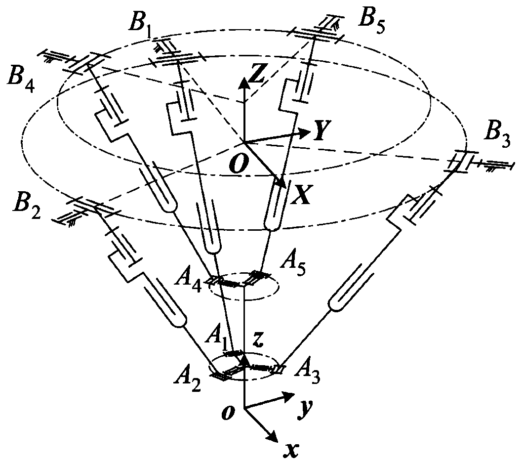
[0077] Such as image 3 As shown, the motion diagram when the parallel processing equipment is a five-axis parallel processing robot. Among them, branch 1 is U P RR configuration, where U is a universal joint, P is a linear pair, R is a rotary joint, and R is an active joint), branch chains 2 to 5 are U P RU configuration. Node B i and A i (i=1...5) are respectively the center point of the U pair connecting the branch chain i with the frame and the moving platform. Node B 1 , B 2 and B 3 Evenly distributed on a certain circle, the radius of the circle is r 1 , with center O and radius OB 1 , OB 2 and OB 3 The angle between them is denoted as γ. Establish the robot coordinate system {rt:O-XYZ} at the center O of the circle, and the reverse extension line of the X axis passes through the node B 1 , the Z axis is perpendicular to the circle. Node B 4 and B 5 Symmetrically distributed on both sides of the surface XOZ, while distributed in a certain radius r 2 , th...

Embodiment approach 2

[0124] From the analysis in Embodiment 1, it can be seen that the error model of the five-axis parallel robot is:

[0125]

[0126] It is known that for a five-axis parallel processing robot, the spatial pose of the spindle can be uniquely determined by three points that are relatively fixed and not collinear. Therefore, in this embodiment, the following method is used to measure the position of the three points: the auxiliary workpiece and the spindle tool handle are clamped and then fixed, and the target ball is sequentially detected and placed on the target seat C 1 、C 2 、C 3 The location coordinates at time. At the same time, in order to unify the measurement results in the robot coordinate system, an auxiliary workpiece coordinate system {at:o * -x * the y * z *}, where the origin o * with point C 1 Coincident, x * Axis points to point C 2 ,z * axis and plane C 1 C 2 C 3 vertical. Let point C i (i=1,2,3) The theoretical position coordinates in the coord...


PUM


Abstract

The embodiment of the invention provides a kinematic calibration method for parallel machining equipment, and belongs to the technical field of kinematic calibration. The kinematic calibration methodcomprises the steps that a first error model of the parallel machining equipment is established according to a terminal pose data acquisition mode of the parallel machining equipment; measure pose combination for recognizing of the parallel machining equipment is optimized, first position data corresponding to a target point of the parallel machining equipment are measured, and a recognition modelof the parallel machining equipment is established; according to a current first error parameter of the parallel machining equipment, second position data corresponding to the target point of the parallel machining equipment are measured; the first position data and the second position data are input to the recognition model of the parallel machining equipment to obtain a second error parameter;and a current error parameter of the parallel machining equipment is updated to the second error parameter from the first error parameter. According to the scheme of the kinematic calibration method,the recognition precision and the recognition efficiency of the error parameter of the determined parallel machining equipment are improved.

Description

technical field [0001] The present disclosure relates to the technical field of kinematics calibration, in particular to a kinematics calibration method for parallel processing equipment. Background technique [0002] With the development of my country's automobile, shipbuilding, aviation, aerospace and other industries, the requirements for fast and integrated processing capabilities of complex curved surface modeling parts and large cutting volume structural parts are also getting higher and higher. At present, the main processing equipment used is multi-axis CNC machine tools. However, this type of machine tool faces many limitations in improving the processing efficiency, including the tandem machine tool structure, which will cause large mass of moving parts and low energy utilization rate during processing; The tandem double-rotation motion of the five-axis CNC machine tool will have problems such as long invalid path during processing and automatic rotation when cross...

Claims


Application Information

Patent Timeline
Patent Type & Authority Applications(China)
IPC IPC(8): B25J9/00B25J9/16
CPCB25J9/003B25J9/1664
Inventor 刘辛军谢福贵罗璇
Owner TSINGHUA UNIV
Why Eureka
Try Eureka