Eureka AIR delivers breakthrough ideas for toughest innovation challenges, trusted by R&D personnel around the world.

Pulse power supply system based on generator cluster and energy storage microgrid and discharging method

A pulse power supply and generator technology, applied in the direction of AC network load balance, single network parallel feeding arrangement, etc., can solve the problem that the remaining energy of the pulse generator cannot be fully utilized, so as to increase the proportion of inertial kinetic energy, increase the conversion ratio, and improve The effect of energy utilization

Active Publication Date: 2020-03-06
INST OF ELECTRICAL ENG CHINESE ACAD OF SCI
View PDF6 Cites 2 Cited by
  • Summary
  • Abstract
  • Description
  • Claims
  • Application Information

AI Technical Summary

Problems solved by technology

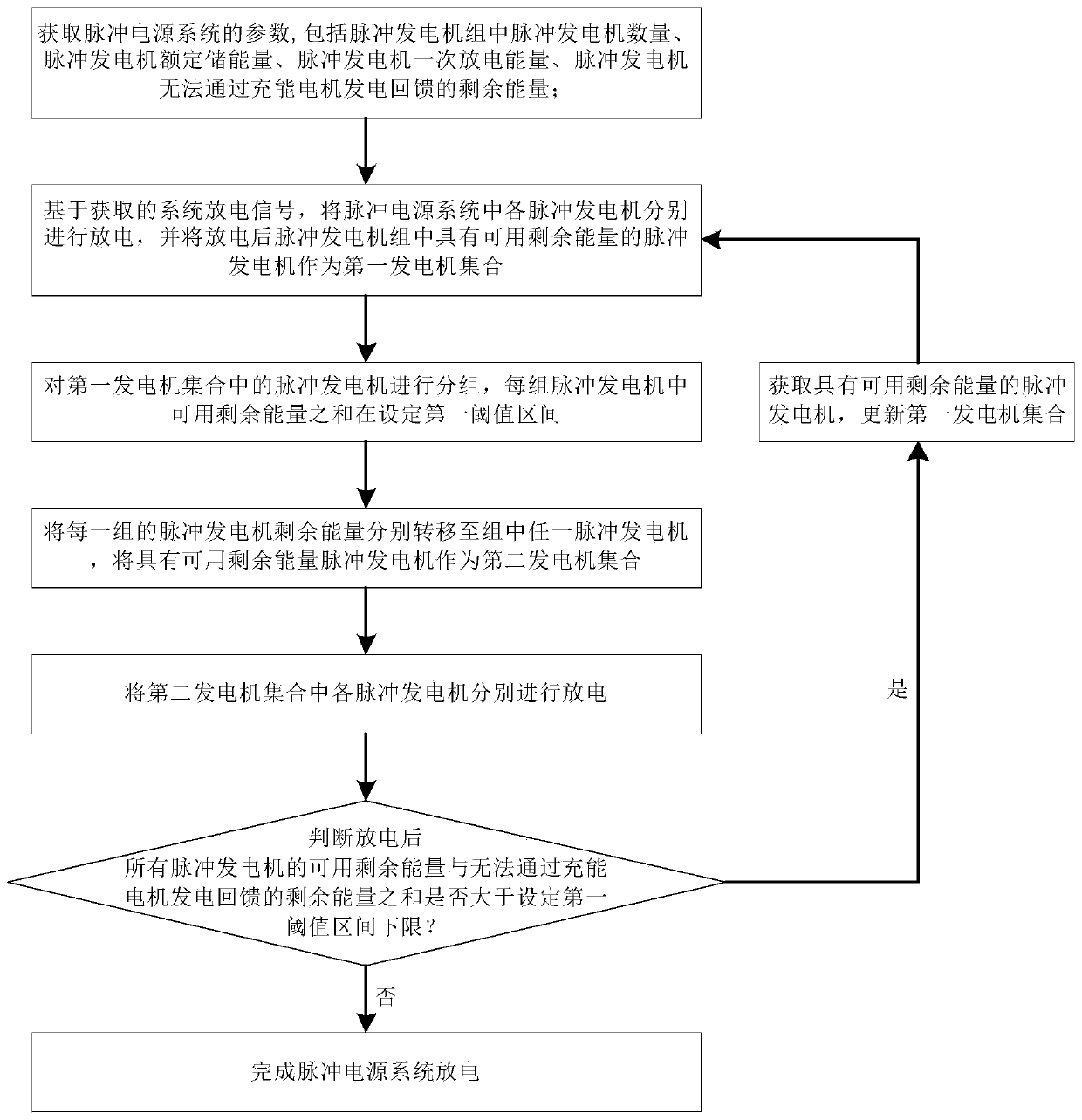
[0005] In order to solve the above-mentioned problems in the prior art, that is, the problem that the remaining energy of the pulse generator in the prior art cannot be fully utilized, the present invention provides a discharge method for a pulse power supply system based on generator clusters and energy storage microgrids. The pulse power supply System discharge methods include:

Method used

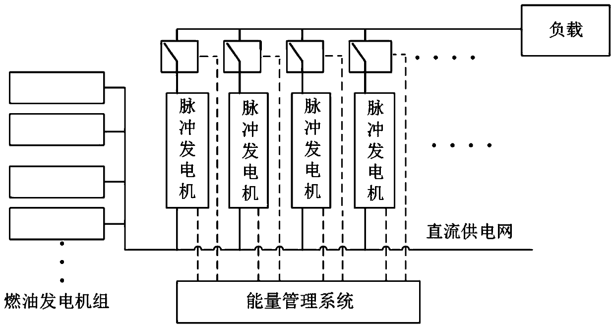
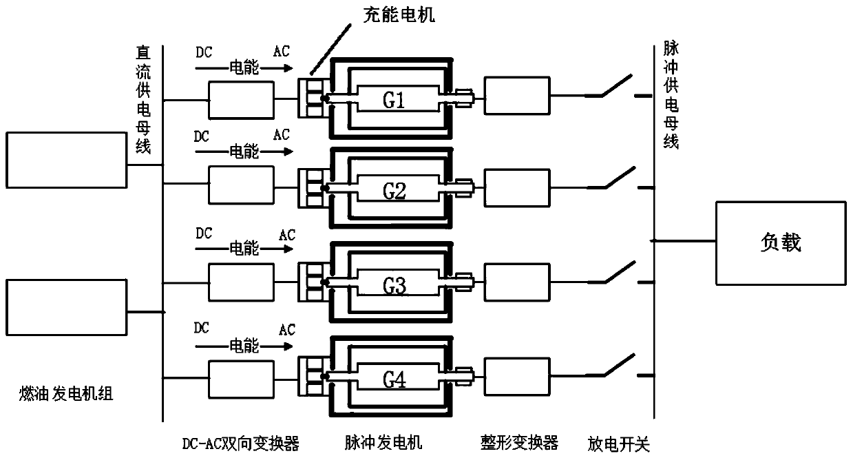

Image

  • Pulse power supply system based on generator cluster and energy storage microgrid and discharging method
  • Pulse power supply system based on generator cluster and energy storage microgrid and discharging method
  • Pulse power supply system based on generator cluster and energy storage microgrid and discharging method

Examples


Embodiment Construction

[0050] The application will be further described in detail below in conjunction with the accompanying drawings and embodiments. It should be understood that the specific embodiments described here are only used to explain related inventions, not to limit the invention. It should also be noted that, for the convenience of description, only the parts related to the related invention are shown in the drawings.

[0051] It should be noted that, in the case of no conflict, the embodiments in the present application and the features in the embodiments can be combined with each other. The present application will be described in detail below with reference to the accompanying drawings and embodiments.

[0052] A discharge method of a pulse power supply system based on generator clusters and energy storage microgrids of the present invention, the discharge method of the pulse power supply system includes:

[0053] Step S10, obtain the parameters of the pulse power supply system; the...


PUM


Abstract

The invention belongs to the field of pulse power generation, particularly relates to a pulse power supply system based on a generator cluster and an energy storage microgrid and a discharging method,and aims to solve the problem that residual energy of a pulse generator cannot be fully utilized in the prior art. The method comprises the following steps: respectively discharging each pulse generator based on a system discharge signal and parameters; grouping the pulse generators, and transferring the residual energy of each group to any pulse generator in the group; discharging again, grouping the pulse generators with available residual energy, and performing energy transfer again; and iteratively discharging the pulse generator set until the rotating speed of the pulse generator is reduced to the condition that discharge and the power generation indexes do not meet the requirements. According to the invention, by utilizing the characteristic that through the controllable rectification of charging motor, constant-voltage power generation can be carried out in a wide rotating speed range, so residual energy can be transferred in the pulse generator cluster, the conversion ratio from inertia kinetic energy to pulse electric energy is improved from the system level, and the energy utilization rate is improved.

Description

technical field [0001] The invention belongs to the field of pulse power generation, and in particular relates to a pulse power supply system and a discharge method based on generator clusters and energy storage microgrids. Background technique [0002] The pulse generator is a special rotating electrical machine that integrates flywheel energy storage, electromechanical energy conversion and pulse discharge. The discharge energy density of the pulse power supply system based on the pulse generator can reach 2-3 times that of the capacitor, which is conducive to the miniaturization of the pulse power supply. At present, most of the large-scale pulse generators developed at home and abroad have a single inertial energy storage of no more than 50MJ, and most of the single pulse discharge energy does not exceed 4MJ, which cannot meet the demand. Therefore, it is necessary to use multiple sets of pulse generators in parallel. total discharge energy. The pulse power supply syst...

Claims


Application Information

Patent Timeline
Patent Type & Authority Applications(China)
IPC IPC(8): H02J3/38H02J3/30
CPCH02J3/30H02J3/38Y02E60/16
Inventor 王又珑梁斌温旭辉张颖
Owner INST OF ELECTRICAL ENG CHINESE ACAD OF SCI
Why Eureka
Eureka Blog
Learn More