
Antenna module and terminal

An antenna module and antenna technology, applied to antennas, slot antennas, antenna components, etc., can solve problems such as narrow working bandwidth, low antenna working efficiency, and narrow internal space of terminals

Active Publication Date: 2020-03-06
GUANGDONG OPPO MOBILE TELECOMM CORP LTD
View PDF3 Cites 2 Cited by
  • Summary
  • Abstract
  • Description
  • Claims
  • Application Information

AI Technical Summary

Problems solved by technology

[0004] As the internal space of the terminal becomes narrower and narrower, the space left for the antenna is also less and less, resulting in problems such as low working efficiency and narrow working bandwidth of the antenna.

Method used


Image

  • Antenna module and terminal
  • Antenna module and terminal
  • Antenna module and terminal

Examples


Embodiment Construction

[0027] Exemplary embodiments will be described in detail herein, examples of which are illustrated in the accompanying drawings. Where the following description refers to the drawings, the same numerals in different drawings refer to the same or similar elements unless otherwise indicated. The implementations described in the illustrative examples below are not intended to represent all implementations consistent with this application. Rather, they are merely examples of apparatus and methods consistent with some aspects of the present application as recited in the appended claims.

[0028] The solution provided by this application can be used in a terminal used in daily life. When designing an antenna in a terminal, in a real-world scenario of multi-band application, for ease of understanding, the following first describes some terms involved in the embodiments of this application and The application scenarios are briefly introduced.

[0029] MIMO (Multiple-Input Multiple-O...


PUM


Abstract

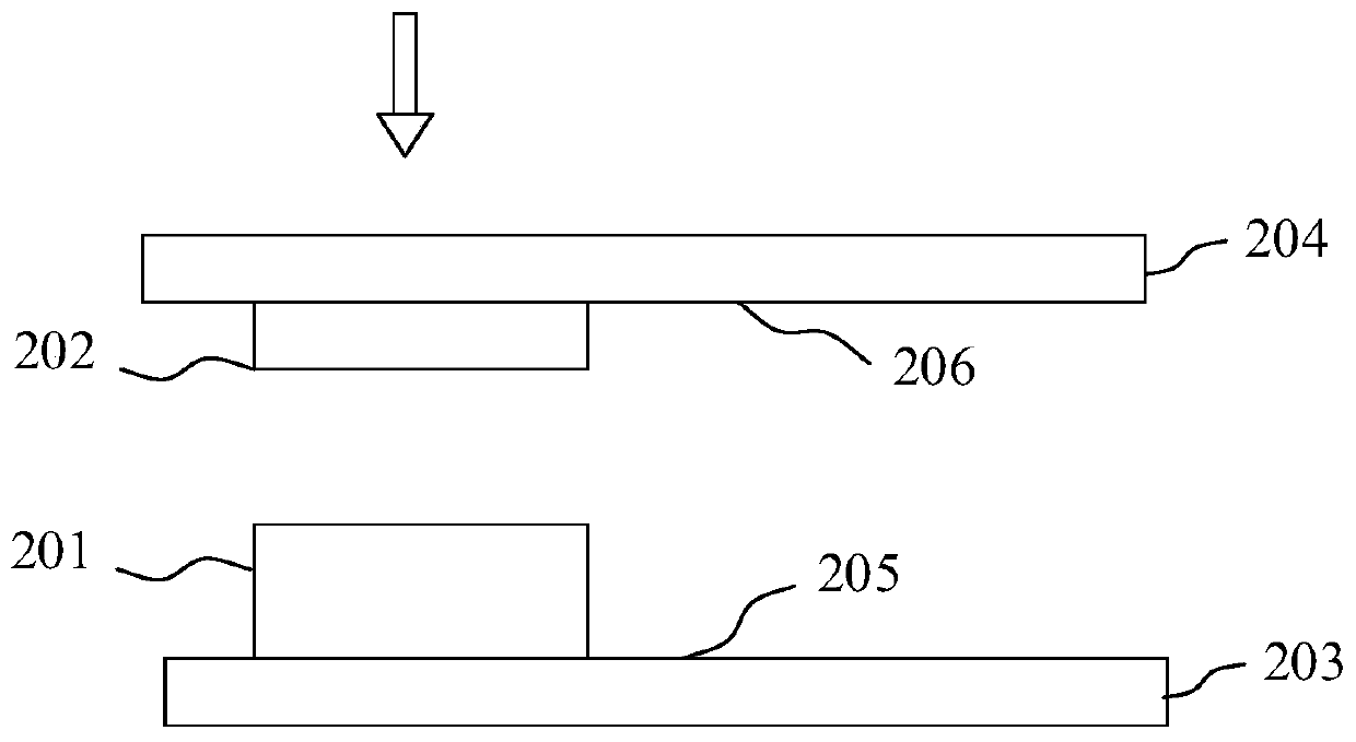
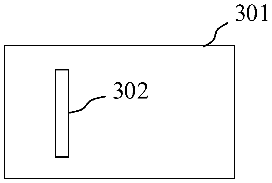
The invention discloses an antenna module and a terminal, and belongs to the technical field of antennas. The antenna module comprises a first antenna, a coupling enhancement structure, a first substrate and a second substrate, wherein the first surface of the first substrate is opposite to the second surface of the second substrate, the first antenna is arranged on the first surface of the firstsubstrate, and the coupling enhancement structure is arranged on the second surface of the second substrate; the coupling enhancement structure comprises a radiation slot, and the radiation slot corresponds to the position of a current strong point on a radiator of the first antenna; the current strong point is the position with the maximum current on the radiator of the first antenna when the first antenna works in a first working mode; and the length extension direction of the radiation slot is perpendicular to the current direction on the radiator of the first antenna. According to the application, the current strong point on the first antenna is changed through self coupling of the coupling enhancement structure, so that the resonant frequency is changed, the radiation bandwidth of theantenna is expanded, and the radiation efficiency of the antenna is improved.

Description

technical field [0001] The present application relates to the field of antenna technology, and in particular, to an antenna module and a terminal. Background technique [0002] With the rapid development of the field of antenna technology, various antennas have been used in terminals, among which, the quality of signals transmitted by the antenna is often one of the concerns of users. [0003] In a terminal, due to the requirements of various applications, there are more and more hardware devices in the terminal, and these hardware devices occupy more and more internal space of the terminal, which limits the arrangement of terminal antennas. For example, the terminal needs to use a display screen such as a full screen, a curved screen, and a surround screen, or the terminal needs to support various types of cameras for shooting, or the terminal needs to have a larger battery capacity, and so on. In addition, with the development of communication technology, the transmission...

Claims


Application Information

Patent Timeline
IPC IPC(8): H01Q1/36H01Q13/10H01Q1/24H01Q1/22H04M1/02
CPCH01Q1/36H01Q13/10H01Q1/242H01Q1/2258H01Q1/22H04M1/026
Inventor 雍征东
Owner GUANGDONG OPPO MOBILE TELECOMM CORP LTD
Learn More