
Camera position optimization method based on visibility

An optimization method and camera technology, applied in the field of computer vision, can solve problems such as inability to guarantee global optimality, faults, limitations, etc.

Pending Publication Date: 2020-02-28
JIANGSU UNIV OF SCI & TECH
View PDF2 Cites 1 Cited by
  • Summary
  • Abstract
  • Description
  • Claims
  • Application Information

AI Technical Summary

Problems solved by technology

The Chinese patent "A method and device for automatically determining the position of the camera" (Patent No.: CN201610793372.3) proposes to identify the set of information points in the surrounding scene based on the captured video images, and to identify the latitude and longitude of the camera. Although this method is limited to a certain extent It improves the efficiency of calibrating the camera position, but it is only limited to the position of a single camera
It turns out to be reliable for handling these examples in his work, but as he points out, it does not guarantee global optimum
While it reduces the complexity of FIS design, it can lead to failures when visual constraints and precision enhancements have high inconsistencies

Method used


Image

  • Camera position optimization method based on visibility
  • Camera position optimization method based on visibility
  • Camera position optimization method based on visibility

Examples


Embodiment Construction

[0026] The technical scheme of the present invention will be described in detail below in conjunction with the accompanying drawings.

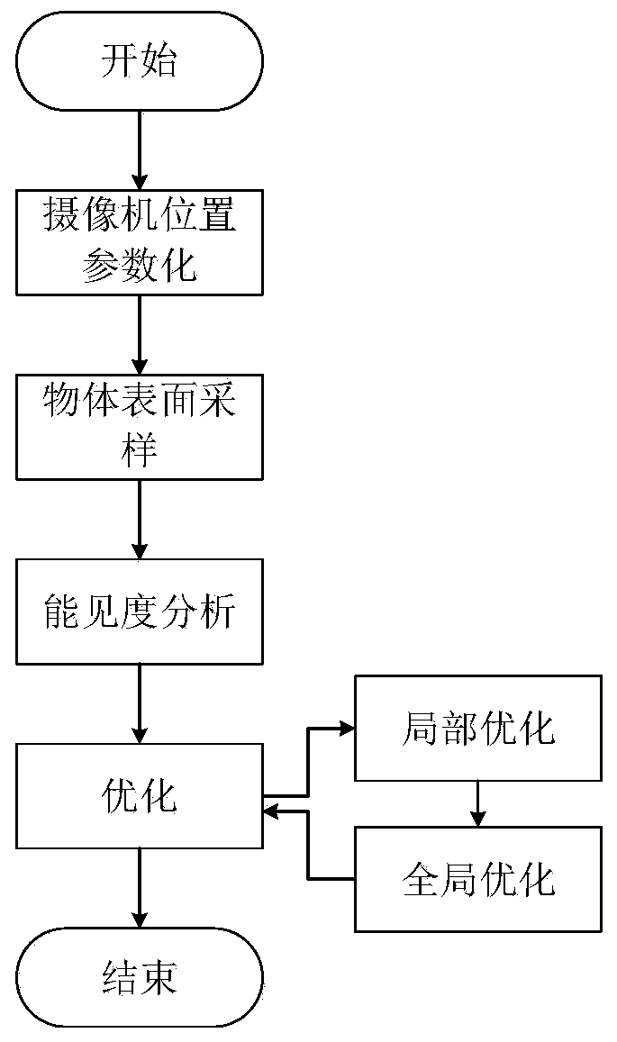
[0027] Such as figure 1 As shown, a visibility-based camera position optimization method, firstly, the camera position movement space is parameterized by mathematical calculation, and then the surface of interest is sampled to points used to represent the surface of the object. By sampling the surface and parameterizing the camera position, the object's surface visibility is analyzed and the camera position is optimized by a fitness function. In the optimization process, the first step is to complete the single camera position optimization, which is denoted as local optimization and camera position optimization. The second step, in the global layout, is detected according to the standard, which is recorded as global optimization. The third step is to perform further optimization according to the results of the global optimization, and contin...


PUM


Abstract

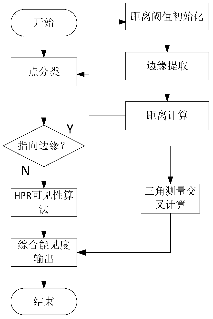
The invention discloses a camera position optimization method based on visibility, and the method comprises the steps: firstly, representing the surface of an object as a sampling point, and parameterizing a potential camera position as a function of a relative posture; secondly, performing point visibility analysis by adopting a hidden point removal algorithm; then, in consideration of visibilityand ray angles between different camera positions, performing camera position optimization through a genetic algorithm, measurement accuracy will be greatly affected according to an accuracy theory in close-range photogrammetry, and then performing optimization circulation until the ratio of the coverage degree of surface points is satisfied. According to the method, the optimized positions of aplurality of cameras are obtained, and the method can be used for automatic manufacturing metering application.

Description

technical field [0001] The invention relates to computer vision, in particular to a visibility-based camera position optimization method. Background technique [0002] With the development of machine vision technology, visual measurement has gradually become the focus of research in the field of industrial manufacturing metrology. A typical vision measurement architecture includes camera positioning, firmware settings, image acquisition, image processing, reconstruction, and data output. As the basic part of the whole visual measurement, camera positioning is particularly important. But camera positioning is the most susceptible and can only be carried out by experienced specialists under certain conditions. Researchers have worked hard on this issue, but there are still problems that have not been solved. [0003] A visibility-based camera position optimization method is a new type of camera position recognition method, which has the advantages of simple calculation and ...

Claims


Application Information

Patent Timeline
IPC IPC(8): G06F30/20
Inventor 张辉王玉张胜文程德俊李群
Owner JIANGSU UNIV OF SCI & TECH
Learn More