
Support for testing optical fiber gyroscope

A fiber optic gyroscope and screw technology, applied in the direction of measuring devices, instruments, etc., can solve the problems of inconvenient clamping and positioning of fiber optic gyroscopes, and achieve the effects of improving clamping protection capabilities, convenient use, and avoiding deformation

Inactive Publication Date: 2020-02-28
衡阳市和仲通讯科技有限公司
View PDF10 Cites 1 Cited by
  • Summary
  • Abstract
  • Description
  • Claims
  • Application Information

AI Technical Summary

Problems solved by technology

There are some deficiencies in the above patents: it is inconvenient to clamp and position the fiber optic gyroscope

Method used


Image

  • Support for testing optical fiber gyroscope
  • Support for testing optical fiber gyroscope
  • Support for testing optical fiber gyroscope

Examples


Embodiment 1

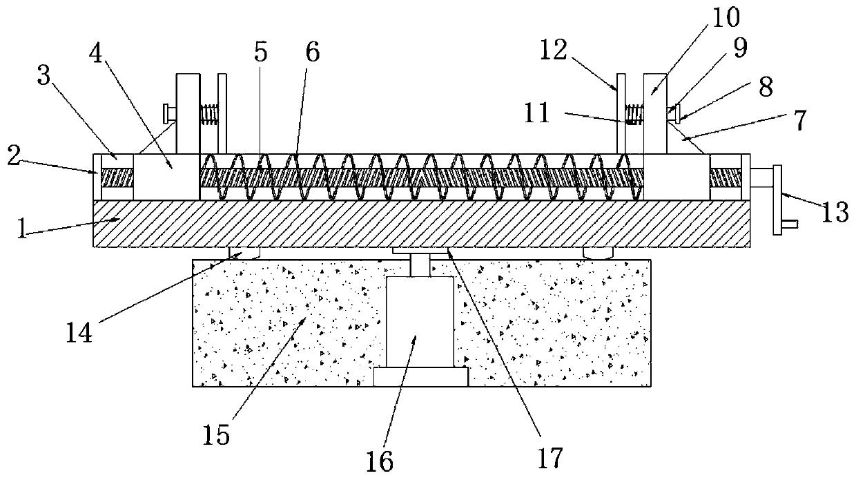
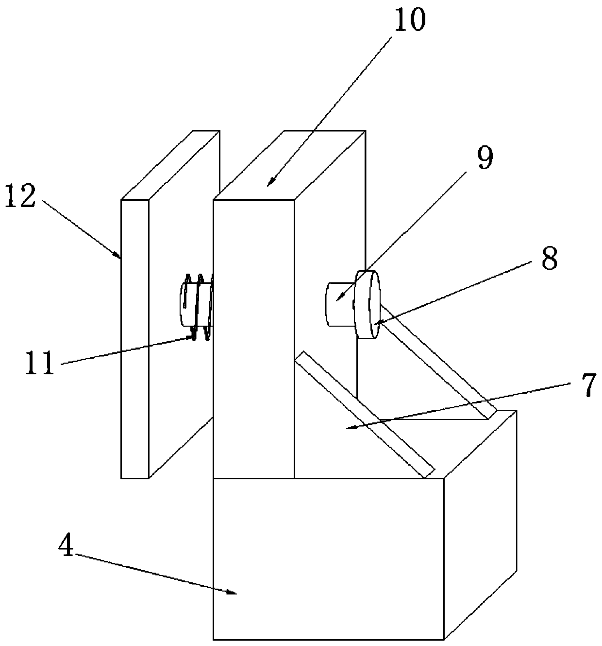
[0024] refer to figure 1 and figure 2 , a bracket for fiber optic gyro testing, including a storage board 1, a chute 3 is opened on the outer wall of the top of the storage board 1, and both ends of the chute 3 are fixed with fixed plates 2, and two fixed plates 2 are rotated and inserted with screw rods 5. There are two sections of thread in opposite directions on the screw 5, and the two sections of the screw 5 are both threaded with a slider 4 that forms a sliding fit with the chute 3, and the support spring 6 is sleeved on the screw 5, and the support spring 6 is located at the Between the two sliders 4, a support plate 10 is fixed on the top of the slider 4, and a movable rod 9 is movably inserted on the support plate 10, and the two ends of the movable rod 9 are respectively fixed with a limit block 8 and a clamping plate 12, and the movable rod 9 A clamping spring 11 is sleeved on one end close to the clamping plate 12 .

[0025] One end of the screw rod 5 is fixed w...

Embodiment 2

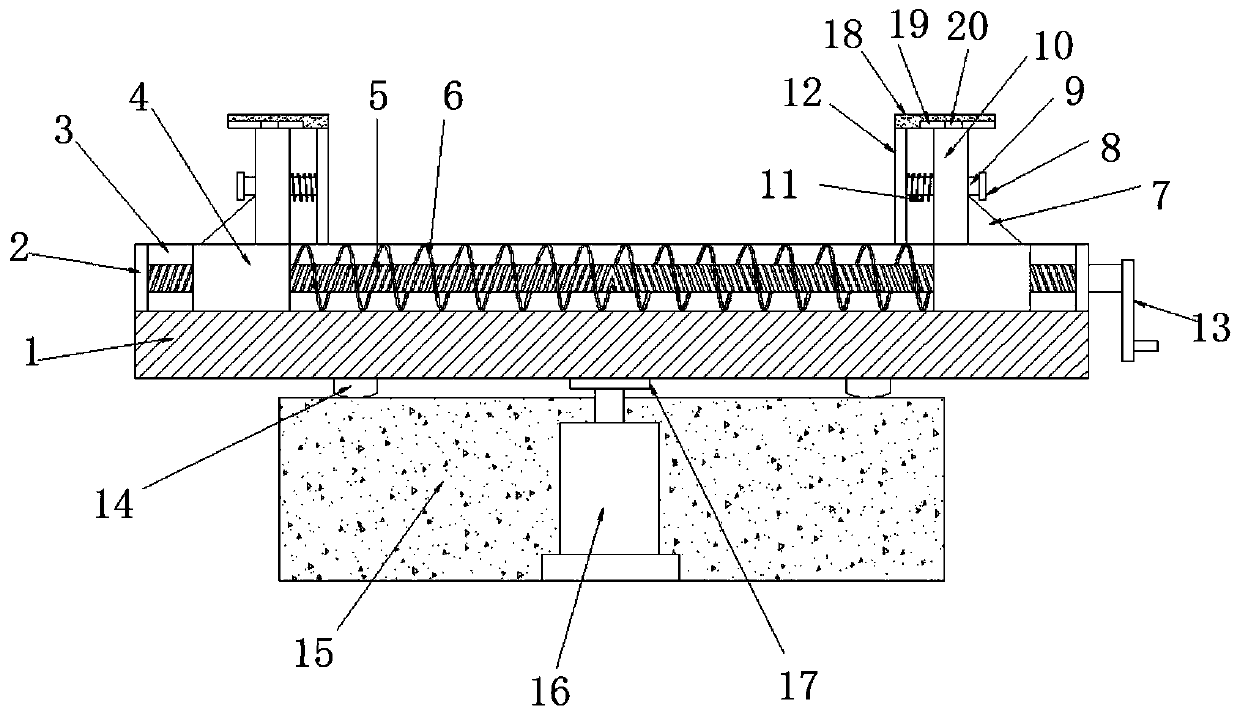
[0028] refer to image 3 , a bracket for fiber optic gyro testing. The difference between this embodiment and Embodiment 1 is that a guide plate 18 is also fixed on the top outer wall of the clamping plate 12, and the bottom outer wall of the guide plate 18 is attached to the top outer wall of the support plate 10, and the guide plate 18 A guide groove 19 is formed on the outer wall of the bottom, and a guide block 20 is fixed on the top of the support plate 10 to form a snap fit with the guide groove 19 .

[0029] The working principle of this embodiment: the guide plate 18 can form a relative slide with the top of the support plate 10 when the clamping plate 12 performs clamping work, and play a position-limiting guiding role for the clamping plate 12 to improve the stability of the clamping work, while The guide block 20 can cooperate with the guide groove 19 on the guide plate 18 to limit and guide the guide plate 18 to improve the stability of the lateral movement of the ...


PUM


Abstract

The invention discloses a support for testing an optical fiber gyroscope. The support comprises a storage plate, wherein a sliding groove is formed in the outer wall of the top of the storage plate; fixing plates are fixed at the two ends in the sliding groove; a screw rod is rotationally inserted into the two fixing plates; two sections of threads with opposite directions are formed in the screwrod; the two sections of the screw rod are in threaded sleeve connection with sliding blocks which are in sliding fit with the sliding groove; a supporting spring is connected to the screw rod in a sleeving mode; the supporting spring is positioned between the two sliding blocks; a supporting plate is fixed at the tops of the sliding blocks; a movable rod is movably inserted into the supporting plate; a limiting block and a clamping plate are fixed at the two ends of the movable rod correspondingly; and a clamping spring is connected to the end, close to the clamping plate, of the movable rodin a sleeving mode. According to the support, the optical fiber gyroscope placed on the storage plate can be clamped and fixed on the two sides, so that the overall stability of the optical fiber gyroscope placement work is improved, and the use is convenient.

Description

technical field [0001] The invention relates to the technical field of fiber optic gyroscope testing, in particular to a bracket for fiber optic gyroscope testing. Background technique [0002] The gyroscope is a device for detecting angular motion around one or two axes perpendicular to the rotation axis by using the momentum moment sensitive shell of the high-speed rotating body relative to the inertial space. Angular motion detection devices made of other principles that perform the same function are also called gyroscopes. Modern fiber optic gyroscope is an instrument that can accurately determine the orientation of moving objects. It is an inertial navigation instrument widely used in modern aviation, navigation, aerospace and national defense industries. Its development is of great importance to a country's industry, national defense and The development of other high-tech has very important strategic significance. [0003] After retrieval, the Chinese Patent Publicat...

Claims


Application Information

Patent Timeline
Patent Type & Authority Applications(China)
IPC IPC(8): G01C25/00
CPCG01C25/00
Inventor 李冬平王秀国胡澜
Owner 衡阳市和仲通讯科技有限公司
Learn More