
Plastic liner fiber fully-wound gas bottle mouth structure

A technology for wrapping gas cylinders and inner liner, applied in fixed-capacity gas storage tanks, installation devices for container construction, gas/liquid distribution and storage, etc., can solve safety hazards, hydrogen leakage, and large differences in modulus and thermal expansion rate and other problems, to achieve the effect of self-sealing, reliable connection and convenient installation

Pending Publication Date: 2020-02-28
ZHANGJIAGANG FURUI HYDROGEN ENERGY EQUIP CO LTD
View PDF10 Cites 4 Cited by
  • Summary
  • Abstract
  • Description
  • Claims
  • Application Information

AI Technical Summary

Problems solved by technology

Among them, all-metal gas cylinders, metal liner fiber hoop-wound gas cylinders and metal liner fiber fully-wound gas cylinders have a relatively large weight capacity, which is difficult to meet the requirements of hydrogen storage density per unit mass, and is not ideal for vehicle-mounted hydrogen supply systems
However, due to the limitation of the strength of the plastic itself and other factors, the plastic inner fiber full-wound gas cylinder needs to be made of metal materials. Due to the large difference in modulus and thermal expansion rate of the metal and plastic materials, there is a difference between the metal bottle mouth and the plastic bottle mouth. The connection between the inner tanks is not reliable, and there is a risk of hydrogen leakage during use, which poses a great safety hazard

Method used

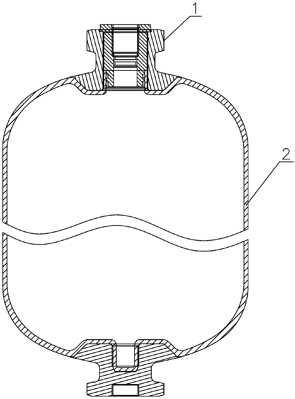
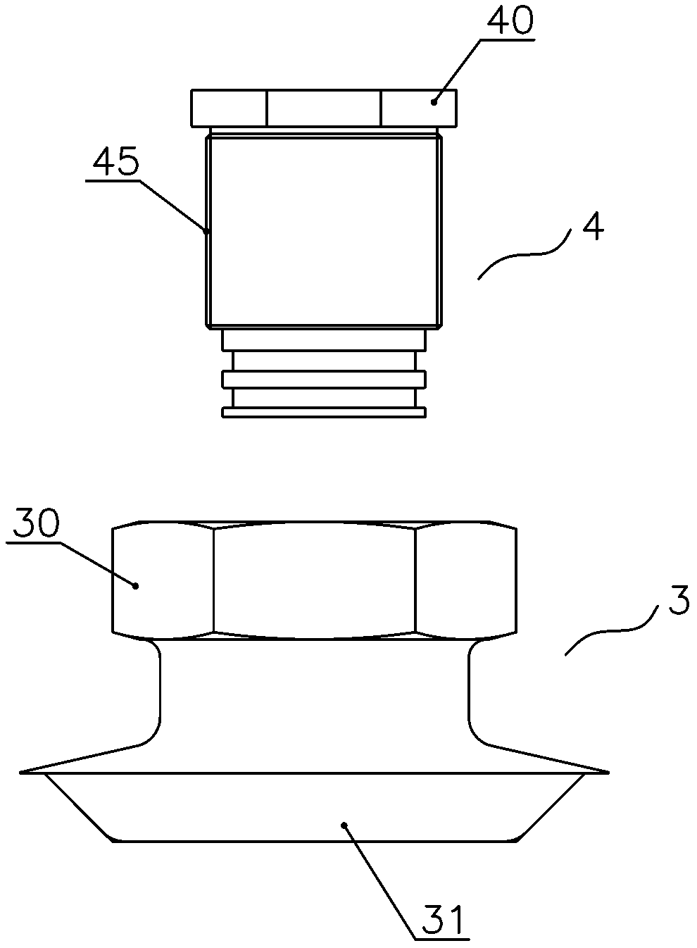

Image

  • Plastic liner fiber fully-wound gas bottle mouth structure
  • Plastic liner fiber fully-wound gas bottle mouth structure
  • Plastic liner fiber fully-wound gas bottle mouth structure

Examples


Embodiment Construction

[0022] The technical solutions of the present invention will be further described in detail below in conjunction with the accompanying drawings and preferred embodiments.

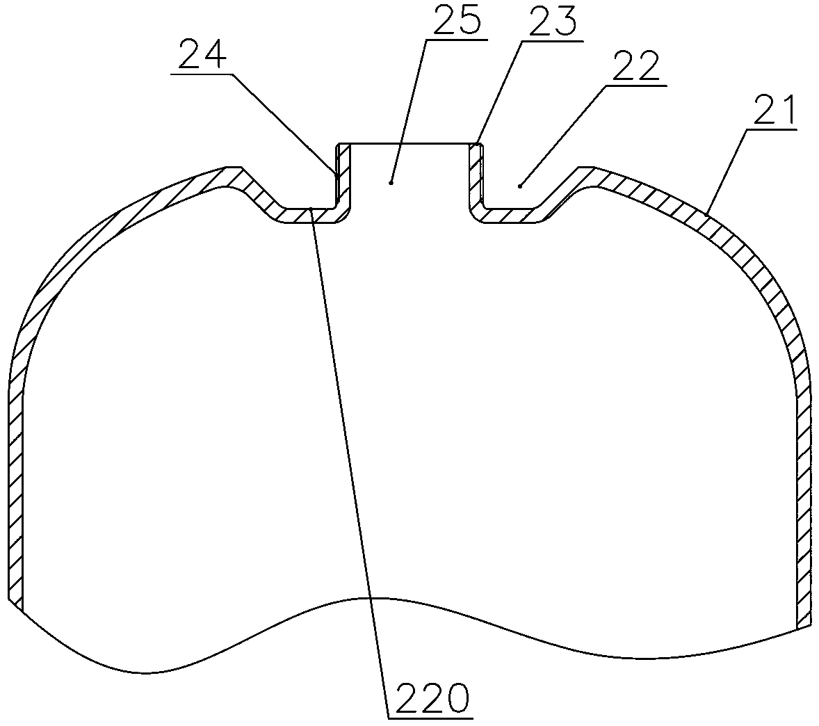
[0023] Such as figure 1 and figure 2 As shown, the mouth structure of a plastic liner fiber fully wound gas cylinder described in this embodiment includes: a metal bottle mouth 1 and a plastic liner 2, and the top of the upper head 21 of the plastic liner 2 is recessed inward to form Embedding groove 22, in the middle of the embedding groove 22, a connecting pipe 23 protruding outwards and coaxial with the plastic liner 2 is provided. The head 21 is integrally formed, and a first external connecting thread segment 24 is arranged on the outer pipe wall of the connecting pipe 23 . In this embodiment, the plastic liner 2, the upper head 21, the lower head, and the connecting pipe 23 are integrally formed by nylon blow molding.

[0024] Such as figure 2 As shown, the groove bottom of the embedding groove ...


PUM


Abstract

The invention discloses a plastic liner fiber fully-wound gas bottle mouth structure. The plastic liner fiber fully-wound gas bottle bottle mouth structure comprises a metal bottle mouth and a plasticliner; the top of an upper sealing head of the plastic liner is recessed inwards to form an embedded groove; a connecting pipe with a first external connecting thread section is arranged in the embedded groove; the metal bottle mouth is composed of an outer joint and an inner joint; an embedded block matched with the embedded groove is arranged at the bottom of the outer joint; a joint internal thread hole in the outer joint penetrates downwards; the embedded block is fixed in the embedded groove and the contour of the embedded block and the outer contour of the upper sealing head are splicedinto a spherical surface; a mounting hole is formed in the inner joint; an inner thread section is formed in the upper section of the mounting hole; the inner joint is composed of an upper cylinder body and a lower cylinder body which are with a second external connecting thread section; the inner joint is screwed in the outer joint through the second external connecting thread section; the lowercylinder body clamps the connecting pipe between the lower cylinder body and the joint inner thread hole; and a first sealing structure is further arranged between the lower cylinder body and an inner hole of the connecting pipe. The structure is convenient to install and good in sealing performance.

Description

technical field [0001] The invention relates to the technical field of hydrogen storage, in particular to a plastic liner fiber fully-wound gas cylinder mouth structure. Background technique [0002] Hydrogen energy is recognized as a clean energy source, and has been valued by people for its advantages such as abundant resources, high combustion value, cleanliness and renewable energy. With the rapid development of fuel cell and battery vehicle technology, safe and efficient hydrogen storage technology has become the key to the application of hydrogen energy. [0003] The hydrogen storage method for vehicles uses gas cylinders to store hydrogen at high pressure and normal temperature. At present, there are four types of gas cylinders: all-metal cylinders, metal liner fiber hoop-wound gas cylinders, metal liner fiber-wrapped gas cylinders, and plastic liner fiber-wound gas cylinders. Winding cylinders. Among them, all-metal gas cylinders, metal liner fiber hoop-wound gas c...

Claims


Application Information

Patent Timeline
Patent Type & Authority Applications(China)
IPC IPC(8): F17C1/16F17C13/06
CPCF17C1/16F17C13/06F17C2201/0104F17C2205/0311
Inventor 何春辉赵亚丽陈甲楠周佳琪苏红艳王学圣王朝崔鸿
Owner ZHANGJIAGANG FURUI HYDROGEN ENERGY EQUIP CO LTD
Learn More