Body anti-collision structure

A body and side panel technology, which is applied in the field of body side impact structure, can solve the problems of inability to solve potential safety hazards, affecting the safety of drivers and passengers, and the limited effect of side impact impact force, so as to improve the side impact resistance and protection of the body. Cabin safety and the effect of strengthening support

Active Publication Date: 2020-11-17
ZHEJIANG GEELY HOLDING (GROUP) CO LTD +1
View PDF5 Cites 0 Cited by
  • Summary
  • Abstract
  • Description
  • Claims
  • Application Information

AI Technical Summary

Problems solved by technology

On the one hand, it is because the size of the anti-side-collision overturn support plate 50 is small, and the effect of absorbing the side-collision impact force is limited.
On the other hand, since the anti-side impact support plate 50 is only lapped on the upper plate 202 of the inner door sill 20 and does not have any fixed contact with the side plate 201 of the inner door sill 20, the inner door sill 20 will The impact force is transmitted to the floor 10 and the anti-side collision support plate 50, and the anti-side collision support plate 50 transmits the impact force to the seat mounting bracket, thereby making the seat mounting bracket 40 at the stress terminal , easy to deform, once the seat mounting bracket 40 is deformed, the seat on it will be tilted, affecting the safety of drivers and passengers
Therefore, this structure still can not solve the safety hazard that automobile body produces because of side collision

Method used


Image

  • Body anti-collision structure
  • Body anti-collision structure
  • Body anti-collision structure

Examples


Embodiment Construction

[0024] In order to further illustrate the technical means and effects adopted by the present application to achieve the intended invention purpose, the following is a detailed description of the present application in combination with preferred embodiments.

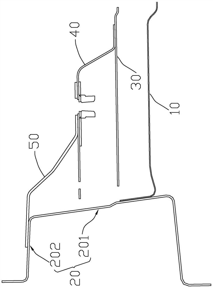
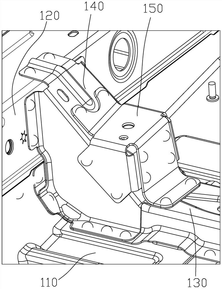
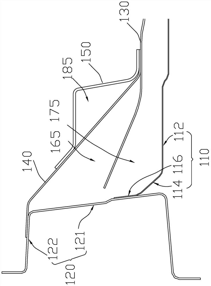
[0025] figure 2 Shown is a three-dimensional schematic view of the anti-side impact structure 100 of the vehicle body of the present application. image 3 Shown is a schematic cross-sectional view of the anti-collision structure 100 of the vehicle body. Such as figure 2 and image 3 As shown, the body side anti-collision structure 100 includes a floor 110, a door sill 120, and a seat mounting beam 130. The door sill 120 includes a side plate 121 and an upper plate 122. The floor 110 is connected to the side plate 121 of the door sill 120. The seat The installation beam 130 is fixed on the floor 110 . The body anti-side impact structure 100 also includes an anti-side impact support plate 140 and a seat mounting brack...


PUM


Abstract

The invention provides a vehicle body side-collision-resistance structure. The vehicle body side-collision-resistance structure comprises a floor, a doorsill, a seat mounting cross beam, a side-collision-resistance supporting plate and a seat mounting bracket. The doorsill comprises a side plate and an upper plate. The side-collision-resistance supporting plate is separately and fixedly connectedwith the upper plate and the seat mounting cross beam, and the side-collision-resistance supporting plate forms a first cavity structure together with the side plate and the seat mounting cross beam;and the seat mounting cross beam forms a second cavity structure together with the floor and the side plate of the doorsill, and the seat mounting bracket is fixed to the side-collision-resistance supporting plate and forms a third cavity structure together with the side-collision-resistance supporting plate. Since the large side-collision-resistance supporting plate is adopted, the supporting strength of the side-collision-resistance supporting plate is strengthened, the supporting area is increased, and the force is dispersed. Through the design of the first cavity structure, the second cavity structure and the third cavity structure, impact kinetic energy can be absorbed, the safety of a driver cabin in a vehicle is protected, and the side-collision-resistance performance of a vehicle body is effectively improved.

Description

technical field [0001] The present application relates to the technical field of automobile body, in particular to an anti-side collision structure of the vehicle body. Background technique [0002] With the development and progress of the automobile industry, the relevant national crash test regulations have become more perfect and stricter, and consumers are paying more and more attention to automobile safety. For example, China's new car evaluation standards put forward stricter and more comprehensive requirements for the evaluation standards of crash safety performance tests for new models on the market than my country's existing mandatory standards. Therefore, when designing a car body, the protection of the occupants in the car should be the first priority, and every effort must be made to minimize the deformation of the cab in the event of a car collision, so as to minimize the damage to the occupants in the car. [0003] Side impact is a very important part of safet...

Claims


Application Information

Patent Timeline
Patent Type & Authority Patents(China)
IPC IPC(8): B62D25/20B60N2/015
CPCB60N2/015B62D25/2036
Inventor 胡智勇张鹤梁虎王连翟胡贤甫汤徐伟
Owner ZHEJIANG GEELY HOLDING (GROUP) CO LTD
Why Eureka
Try Eureka