A glazing device for making Jianzhan
A technology for making and functioning lamps, applied in the field of glazing devices, can solve problems such as troublesome, unstable glaze slurry distribution height, etc., and achieve the effect of uniform distribution height and stable glazing
- Summary
- Abstract
- Description
- Claims
- Application Information
AI Technical Summary
Problems solved by technology
Method used
Image
Examples
Embodiment 1
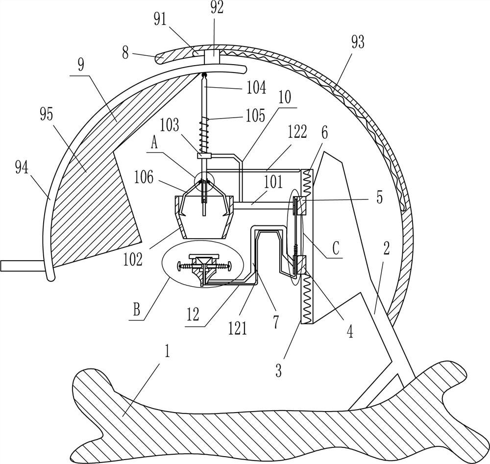
[0019] refer to figure 1 , figure 2 with image 3 , a kind of glazing device for building a cup, including a base 1, a support frame 2, a vertical slide rail 3, a first vertical slide block 4, a second vertical slide block 5, a first spring 6, a first special-shaped Rod 7, arc-shaped plate 8, drive mechanism 9, clamping mechanism 10 and placement block 11, base 1 top right side is fixedly connected with support frame 2, support frame 2 left side is equipped with vertical slide rail 3, vertical sliding Sliding on the rail 3 is provided with the first vertical slide block 4 and the second vertical slide block 5, the first vertical slide block 4 is positioned at the second vertical slide block 5 below, the first vertical slide block 4 bottom and The first spring 6 is connected between the bottom of the vertical slide rail 3, and the first spring 6 is also connected between the top of the second vertical slide block 5 and the top of the vertical slide rail 3. The left side of t...
Embodiment 2
[0024] On the basis of embodiment 1, with reference to figure 1 with figure 2 , the clamping mechanism 10 includes a fixed rod 101, a circular cylinder 102, a guide sleeve 103, a movable rod 104, a third spring 105, a splint 106 and a torsion spring 107, and the left side of the second vertical slider 5 is fixed with a fixed The rod 101, the left end of the fixed rod 101 is fixedly connected with a circular cylinder 102, the circular cylinder 102 is located directly above the placement block 11, the lower part of the inner wall of the circular cylinder 102 is a slope, the guide sleeve 103 is installed on the left side of the top of the fixed rod 101, and the guide sleeve 103 Located directly above the circular cylinder 102, the guide sleeve 103 is provided with a movable rod 104, the top of the movable rod 104 is in contact with the arc rod 94, and a third spring 105 is wound between the upper part of the movable rod 104 and the top of the guide sleeve 103. There are four sp...
Embodiment 3
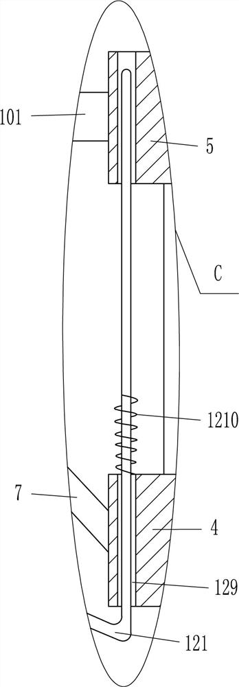
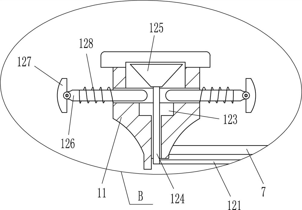
[0027] On the basis of embodiment 1 and embodiment 2, with reference to figure 1 , image 3 with Figure 4 , also includes a fixing mechanism 12 that can fix the built-in cup, the fixing mechanism 12 includes a second special-shaped rod 121, a push rod 122, a slide rod 124, a tapered block 125, a guide rod 126, a movable block 127, and a fourth spring 128 With the fifth spring 1210, there is a special-shaped hole 123 vertically in the middle part of the placement block 11, and a slide bar 124 is slidingly provided in the special-shaped hole 123. Sliding guide rod 126, the inner end of the guide rod 126 is located in the special-shaped hole 123 to cooperate with the tapered block 125, the outer end of the guide rod 126 is hinged with a movable block 127 that can fix the built-in cup, the outside of the guide rod 126 is connected to the outer wall of the placement block 11 A fourth spring 128 is wound between them, and the left parts of the first vertical slider 4 and the seco...
PUM
 Abstract
Description
Claims
Application Information
 - Generate Ideas
- Intellectual Property
- Life Sciences
- Materials
- Tech Scout
- Unparalleled Data Quality
- Higher Quality Content
- 60% Fewer Hallucinations
Browse by: Latest US Patents, China's latest patents, Technical Efficacy Thesaurus, Application Domain, Technology Topic, Popular Technical Reports.
© 2025 PatSnap. All rights reserved.Legal|Privacy policy|Modern Slavery Act Transparency Statement|Sitemap|About US| Contact US: help@patsnap.com


