Virtual atomic clock system for monitoring entity atomic clock and working method

A working method and technology for atomic clocks, applied in the field of atomic clocks, can solve problems such as accurately evaluating the performance of atomic clocks, and achieve the effect of meeting real-time requirements

Active Publication Date: 2020-02-25
NAT INST OF METROLOGY CHINA
View PDF13 Cites 7 Cited by
  • Summary
  • Abstract
  • Description
  • Claims
  • Application Information

AI Technical Summary

Problems solved by technology

Studies have shown that the atomic clocks in the same laboratory are affected by environmental factors, and the noise has a strong correlation, which makes the time scale TA of the clock group unable to be used as a reference to accurately evaluate the performance of the atomic clock

Method used


Image

  • Virtual atomic clock system for monitoring entity atomic clock and working method
  • Virtual atomic clock system for monitoring entity atomic clock and working method
  • Virtual atomic clock system for monitoring entity atomic clock and working method

Examples


Embodiment 1

[0067] Example 1: Random tracking strategy predicts atomic clock behavior:

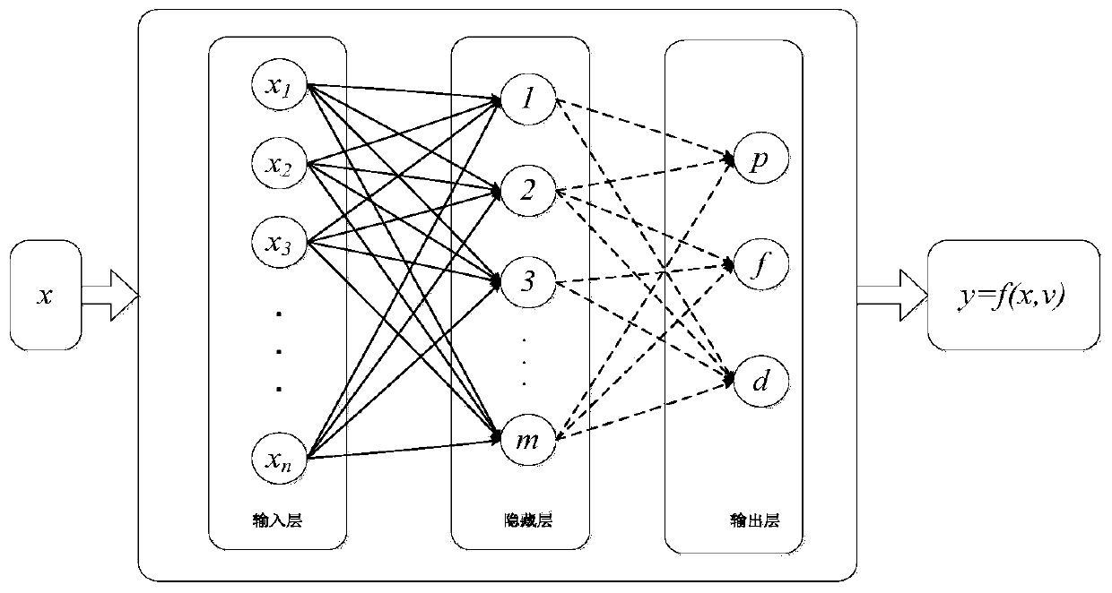
[0068] Embodiment 1 includes a group of predictors, wherein each predictor works in an independent subspace, and the weighted average of all predictors for future predictions is used as the final prediction result, which consists of the following parts:

[0069] (1) Historical data:

[0070] Let X be the measured value vector of atomic clock phase or frequency data, and T be the time interval between each data point.

[0071] X=(x1x2...xn) (1)

[0072] Among them, X represents the historical data sample, that is, the phase difference or frequency difference measured by an atomic clock relative to the reference clock or time scale; xt represents the phase difference or frequency difference at time t, and the vector X is used as the historical data measured by the atomic clock for prediction Future phase or frequency changes of atomic clocks.

[0073] (2) Random grouping

[0074] A random grouping s...

Embodiment 2

[0087] Example 2: LSTM neural network predicts atomic clock behavior:

[0088] In this embodiment 2, a long-short-range memory neural network unit is designed to predict the output frequency information of the atomic clock at the preset time by learning the historical data of the atomic clock. The experimental results compared with the traditional Kalman filter prediction method are as follows Figure 5-Figure 6 shown.

[0089] The electrical components appearing in this article are all connected with the external main controller and 220V mains electricity, and the main controller can be a conventional known device that plays a control such as a computer.

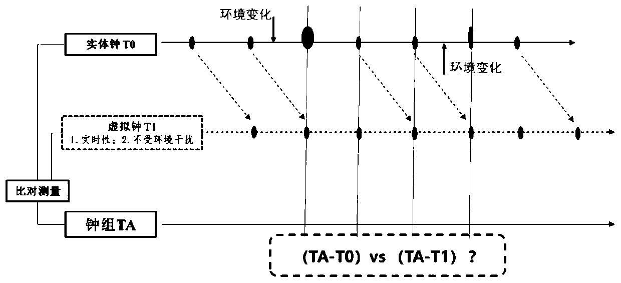
[0090] Compared with the prior art, the present invention proposes to construct a virtualized atomic clock, whose performance is close to the measured one, and use it as a reference to evaluate the performance of the physical atomic clock and monitor the abnormal behavior of the physical atomic clock. The virtual atomic clo...


PUM


Abstract

The invention provides a virtualized atomic clock system, and belongs to the technical field of atomic clocks. Multiple entity atomic clocks obtain relative deviation information relative to a reference TA through a comparison and measurement unit to form an original data set; the original data is analyzed to remove abnormal behaviors, such as random hopping of the phase, the frequency or frequency drifting, of the atomic clocks to form an atomic clock sample data set; historical behaviors of the atomic clocks are learned through an atomic clock prediction and analysis unit by means of an algorithm, deviations of the entity atomic clocks relative to the reference in a preset time are extrapolated to obtain clock deviation data (TA-T1); and the deviations between the entity atomic clocks and the TA at the same moment are acquired, data conversion is conducted, an intermediate reference is eliminated, and relative deviations (T0-T1) between a virtual atomic clock and the entity atomic clocks are obtained. The performance of the virtual atomic clock is close to being measured and is taken as the reference to evaluate the performance of the entity atomic clocks and monitor the abnormalbehaviors of the entity atomic clocks.

Description

Technical field [0001] The invention belongs to the technical field of atomic clocks, and in particular relates to a virtual atomic clock system and working method for monitoring physical atomic clocks. Background technique [0002] In 1967, the Thirteenth International Conference on Weights and Measures passed a resolution defining the basic time unit "second" as the time lasting 9,192,631,770 times the electromagnetic radiation period of the transition between the two hyperfine energy levels of the cesium 133Cs atom ground state. Entering the atomic age, time has become the physical quantity with the highest measurement accuracy in nature. As a timing tool, atomic clocks make the operation of contemporary information society efficient and orderly. Precision time and frequency benchmarks have become indispensable in various fields of the national economy. It is widely used in astronomical observation, geodesy, traffic management, power grid connection and troubleshooting. ...

Claims


Application Information

Patent Timeline
IPC IPC(8): G04D7/00G04F5/14
CPCG04D7/00G04F5/14
Inventor 王玉琢张爱敏高源徐清华
Owner NAT INST OF METROLOGY CHINA
Why Eureka
Try Eureka