Mud removing feeding machine

A feeding machine and feeding technology, which is applied in the field of mining machinery, can solve problems such as abnormal high efficiency, affecting the quality of finished materials, and accumulation of mineral materials on the feeding and conveying surface, so as to improve the excitation effect and efficiency, and the screening effect is ideal , The effect of material screening is sufficient

Inactive Publication Date: 2020-02-25
义乌市金牛环保科技有限公司
View PDF0 Cites 2 Cited by
  • Summary
  • Abstract
  • Description
  • Claims
  • Application Information

AI Technical Summary

Problems solved by technology

[0002] The feeder is an indispensable auxiliary equipment in the crushing production line. The feeder is at the beginning of the production line and sends the raw materials into the crusher for crushing. The feeding surface of the feeder is usually composed of sieve bars. At the same time, it also has a screening function, which is used to separate the soil on the mineral material. Because the soil enters the crushing production line, it will affect the crushing effect, cause the crusher to be blocked, and affect the quality of the finished material. The existing desilting feeder Most of the screen bars are used to form a feeding conveying surface, and the screen bars are arranged in parallel with the same spacing. This structure is likely to cause the mineral material to be blocked in the gap between the screen bars during conveying, unable to advance or fall, and hinder the progress of the mineral material behind. The accumulation of mineral materials on the feeding conveying surface makes it impossible to feed normally and efficiently

Method used


Image

  • Mud removing feeding machine
  • Mud removing feeding machine
  • Mud removing feeding machine

Examples


Embodiment Construction

[0031] The following are specific embodiments of the present invention and in conjunction with the accompanying drawings, the technical solutions of the present invention are further described, but the present invention is not limited to these embodiments.

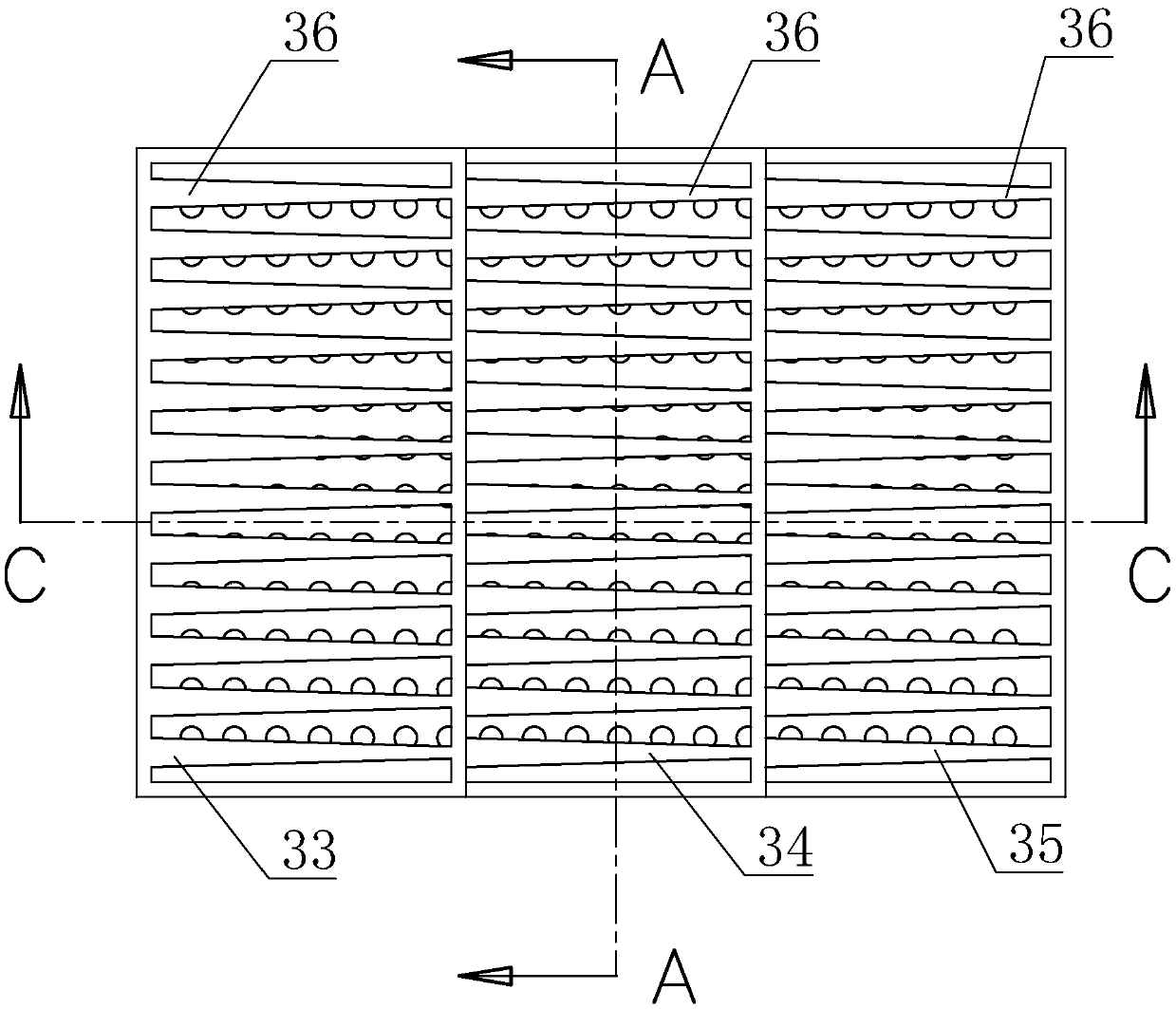
[0032] Please refer to Figure 1-6 As shown, a kind of mud-removing feeder includes a vibrating box 1 and a vibrating device 2; the vibrating box 1 is a hollow structure, and the upper end surface of the vibrating box 1 is a feeding conveying surface 3, and the feeding conveying surface 3 One end is the feed end 31, and the corresponding other end is the discharge end 32. The feeding and conveying surface 3 includes three conveying surfaces, and the three conveying surfaces are continuously connected along the route of mineral material, arranged in order from high to low, forming a ladder For the convenience of description, it is defined as the first conveying surface 33, the second conveying surface 34, and the third conv...


PUM


Abstract

The invention provides a mud removing feeding machine, and belongs to the technical field of mining machines. The mud removing feeding machine comprises a vibration box, and an excitation device for driving the vibration box to vibrate. The upper end face of the vibration box is a feeding conveying face, and the feeding conveying face comprises multiple conveying faces, and the multiple conveyingfaces are in continuous butt joint along the mineral aggregate advancing path and are arranged sequentially from high to low in a ladder shape. Each conveying face is composed of multiple screen bars,and has screening clearances, and the length direction of the screen bars is consistent with the advancing direction of mineral aggregate. The widths of the screen bars are gradually reduced in the mineral aggregate advancing direction, and the screening clearances formed by the screen bars of the same conveying face are gradually enlarged in the mineral aggregate advancing direction. According to the mud removing feeding machine, the feeding conveying face is arranged in the ladder shape, the screen bars of special structures are adopted, blocking happening in the feeding process can be reduced, and a very good mud removing and screening effect is achieved.

Description

technical field [0001] The invention relates to the field of mining machinery, in particular to a mud-removing feeder. Background technique [0002] The feeder is an indispensable auxiliary equipment in the crushing production line. The feeder is at the beginning of the production line and sends the raw materials into the crusher for crushing. The feeding surface of the feeder is usually composed of sieve bars. At the same time, it also has a screening function, which is used to separate the soil on the mineral material. Because the soil enters the crushing production line, it will affect the crushing effect, cause the crusher to be blocked, and affect the quality of the finished material. The existing desilting feeder Most of the screen bars are used to form a feeding conveying surface, and the screen bars are arranged in parallel with the same spacing. This structure is likely to cause the mineral material to be blocked in the gap between the screen bars during conveying, ...

Claims


Application Information

Patent Timeline
Patent Type & Authority Applications(China)
IPC IPC(8): B02C23/02B02C23/14B07B1/28
CPCB02C23/02B02C23/14B07B1/28B07B2201/04
Inventor 朱兴良
Owner 义乌市金牛环保科技有限公司
Why Eureka
Try Eureka