
Beverage straw

A technology for straws and beverages, which is applied to table utensils, home utensils, table utensils, etc., can solve the problems of energy consumption and high production costs, and achieve the effect of easy production, avoiding the danger of puncture or cutting by personnel, and simple composition.

Inactive Publication Date: 2020-02-25
TAIWAN POWER TESTING TECH
View PDF6 Cites 3 Cited by
  • Summary
  • Abstract
  • Description
  • Claims
  • Application Information

AI Technical Summary

Problems solved by technology

[0004] However, high-temperature boilers must be used to manufacture stainless steel drinking straws, and the process consumes a lot of energy, so the production cost is extremely high

Method used


Image

  • Beverage straw
  • Beverage straw
  • Beverage straw

Examples


Embodiment Construction

[0037] In order to describe the technical content of the present invention more clearly, according to the following Figure 1 to Figure 6 Further description will be made in conjunction with specific embodiments.

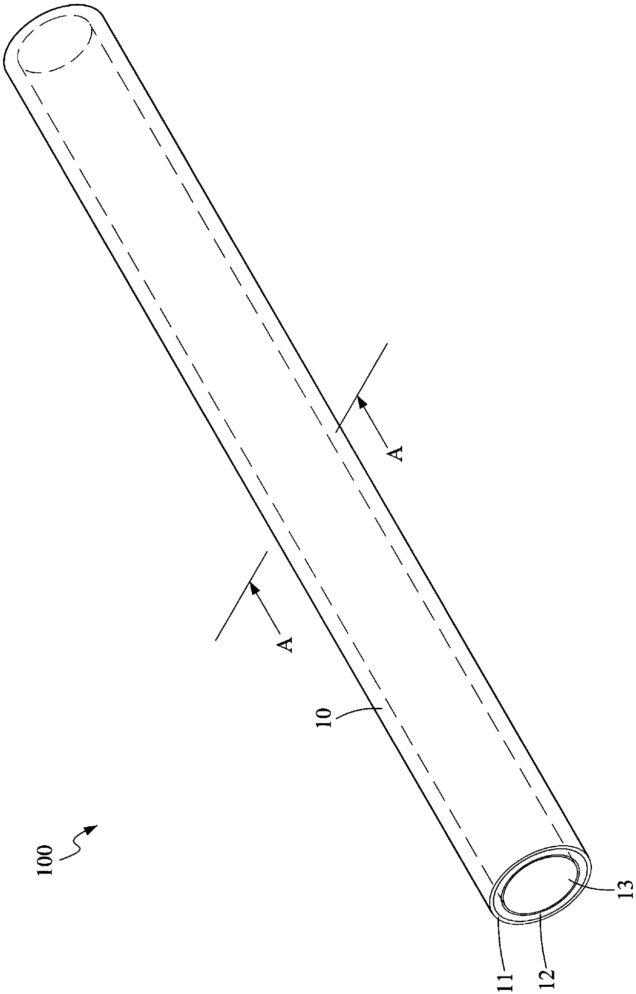
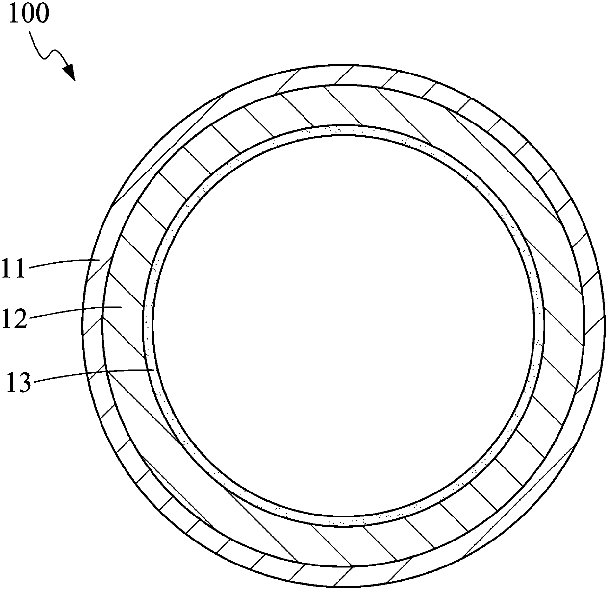
[0038] Such as figure 1 As shown, the drinking straw 100 according to an embodiment of the present invention is a hollow tube body 10 through which two ends are communicated, including an aluminum foil tube layer 11 and a paper tube layer 12, the aluminum foil tube layer 11 and the paper tube layer The material tube layer 12 is completely overlapped inside and outside and bonded together. In addition, the cross-sectional shape of the hollow tube body 10 may also be a polygon such as a circle, a square, or a star. Furthermore, a part of the hollow tube body 10 can also be designed as a bendable corrugated tube, so that the user can adjust the direction of the end.

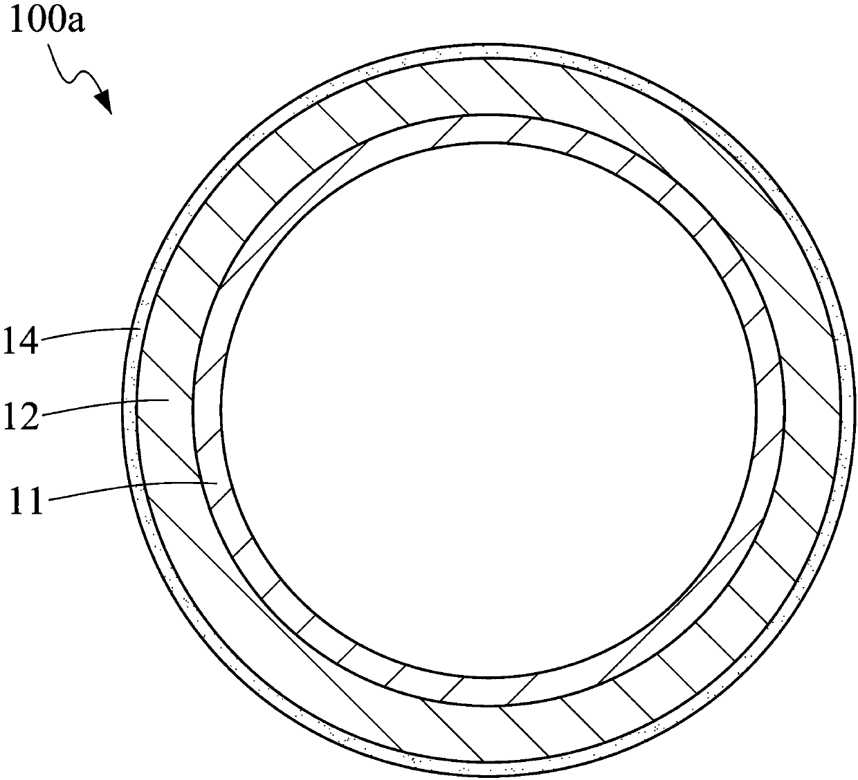
[0039] Such as figure 2 As shown, in the beverage straw 100 according to an embodiment of the pre...


PUM


Abstract

The invention relates to a beverage straw capable of being produced at low cost. The beverage straw is a hollow tube body with two ends communicated in a penetrating mode, and comprises an aluminum foil tube layer and a paper tube layer, wherein the paper tube layer and the aluminum foil tube layer are overlapped completely inside and outside to be laminated.

Description

technical field [0001] The invention relates to a drinking straw, in particular to a low-cost drinking straw. Background technique [0002] Taiwan is located in the subtropical region, and the climate is hot, so cold drink shops are popular, and you can see people everywhere with a cup, which is refreshing and refreshing. In order to carry and drink conveniently, drink straw is attached with cup mostly. In addition to hand-cranked beverage cups, drinks provided by general restaurants and snack bars will also be provided with beverage straws to be consumed by diners. Therefore, the usage rate of beverage straws is extremely high. [0003] However, beverage straws currently on the market are small in size and mostly made of plastic, so the economic value of recycling is low. They are not as important as PET bottles and paper, and are often discarded at will. In addition, plastic drinking straws are difficult to decompose by themselves. Once thousands of plastic drinking stra...

Claims


Application Information

Patent Timeline
Patent Type & Authority Applications(China)
IPC IPC(8): A47G21/18
CPCA47G21/18
Inventor 林裕强
Owner TAIWAN POWER TESTING TECH
Learn More