Dismounting device of traction motor bearing and method applied to device

A traction motor and dismantling device technology, applied in the direction of electromechanical devices, rigid brackets of bearing components, ball bearings, etc., can solve the problems of affecting the production process, long disassembly cycle, cumbersome process, etc., to improve work efficiency, shorten disassembly time, Avoid the effects of the disassembly process

Active Publication Date: 2020-02-21
CSR ZHUZHOU ELECTRIC CO LTD
View PDF4 Cites 11 Cited by
  • Summary
  • Abstract
  • Description
  • Claims
  • Application Information

AI Technical Summary

Problems solved by technology

The entire disassembly period is long, the process is cumbersome, a specific site and special tooling are required, and the maintenance cost and maintenance resource consumption are large
Especially when the faulty bearing needs to be disassembled, the above process cannot be simplified, resulting in a large time span for fault analysis and resolution, which affects the normal production process. The installation method of the traction motor bearing in the prior art is as follows: figure 1 As shown, the rotor 01 is set on the central axis

Method used


Image

  • Dismounting device of traction motor bearing and method applied to device
  • Dismounting device of traction motor bearing and method applied to device
  • Dismounting device of traction motor bearing and method applied to device

Examples


Embodiment Construction

[0043] The following will clearly and completely describe the technical solutions in the embodiments of the present invention with reference to the accompanying drawings in the embodiments of the present invention. Obviously, the described embodiments are only some, not all, embodiments of the present invention. Based on the embodiments of the present invention, all other embodiments obtained by persons of ordinary skill in the art without making creative efforts belong to the protection scope of the present invention.

[0044] The core of the present invention is to provide a dismounting device for traction motor bearings, which can simplify the disassembly process of traction motor bearings. Another core of the present invention is to provide a method applied to the above-mentioned dismounting device of the traction motor bearing.

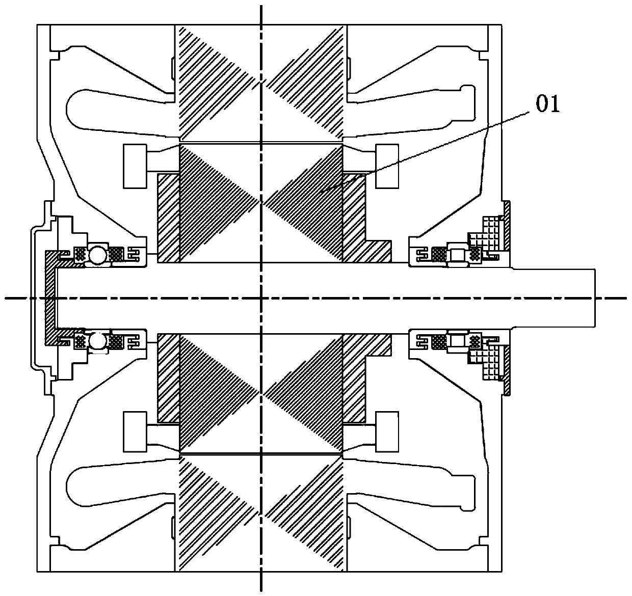
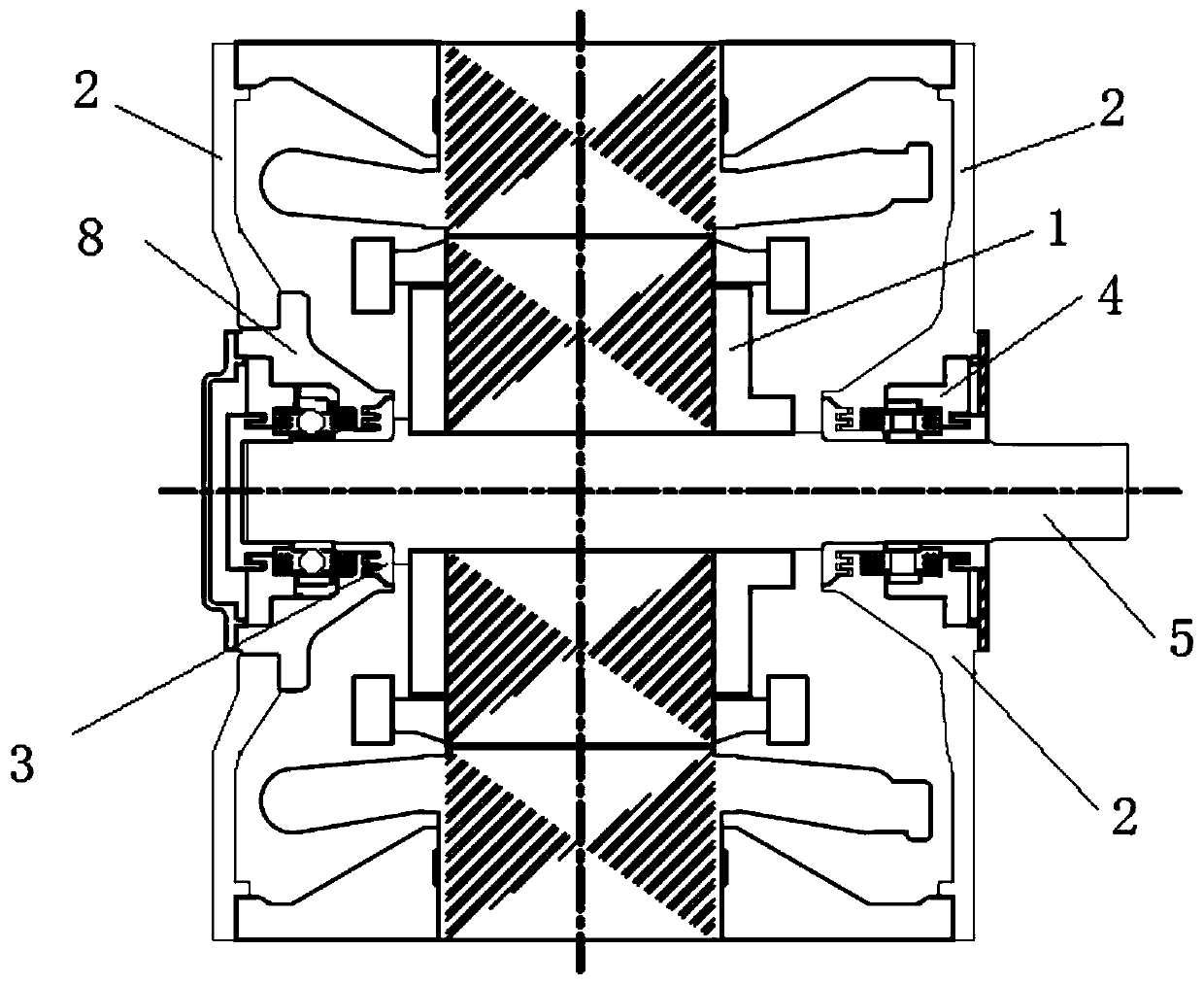
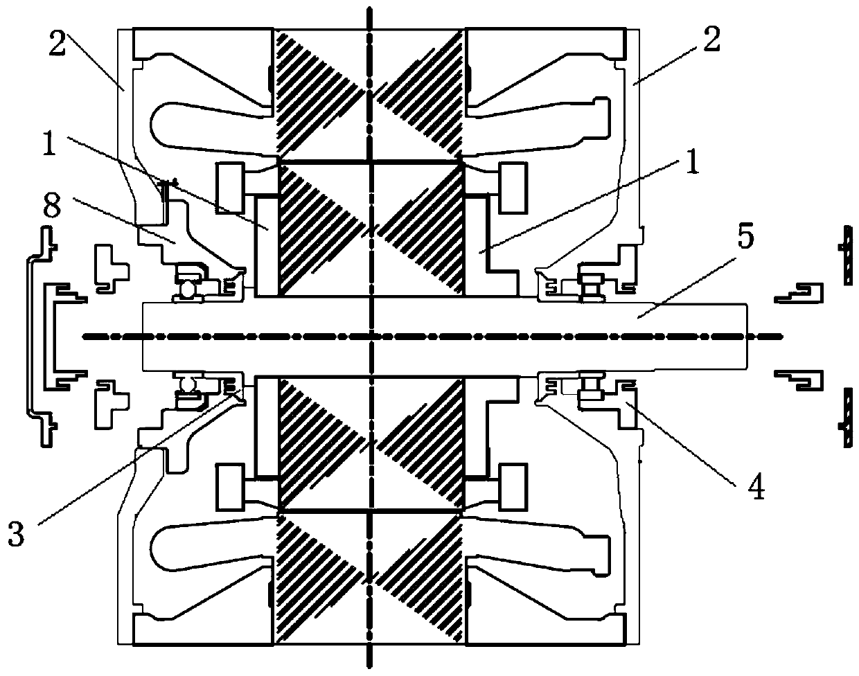
[0045] Please refer to Figure 1-12 , figure 1 It is a structural schematic diagram of a traction motor in the prior art; figure 2 A specifi...


PUM


Abstract

The invention discloses a dismounting device of a traction motor bearing, which comprises a positioning mechanism fixedly arranged on a rotor assembly and a moving mechanism movably arranged relativeto the positioning mechanism, wherein the positioning mechanism is provided with a positioning surface, and the moving mechanism is provided with a matching surface which is used for matching with thepositioning surface to realize radial and axial positioning of the rotor assembly. Compared with the prior art, the dismounting device provided by the invention of the traction motor bearing avoids the bearing dismounting process after the rotor assembly and the stator assembly are separated, so that the dismounting process of the traction motor bearing is simplified, the configuration requirements and cost of human resources and material resources in the bearing dismounting process are reduced, the dismounting time of the traction motor bearing is shortened, and the working efficiency is improved. The invention further discloses a dismounting method of the traction motor bearing, which is applied to the dismounting device of the traction motor bearing.

Description

technical field [0001] The invention relates to the technical field of motor maintenance, and more specifically relates to a device for dismounting a bearing of a traction motor. In addition, the present invention also relates to a method applied to the above-mentioned dismounting device of the traction motor bearing. Background technique [0002] With the rapid development of rail transit, the operation and maintenance requirements and technical level of rail vehicles are also increasing. The bearing of the traction motor is the core force-bearing component. In order to ensure the safe operation of the vehicle, the maintenance of the bearing is extremely critical, and it must be inspected or replaced within the specified time or kilometers. [0003] Traction motor bearings need to be overhauled or replaced regularly. In the prior art, when overhauling or replacing traction motor bearings, the motor needs to be dropped off and returned to the factory, and professional tools...

Claims


Application Information

Patent Timeline
IPC IPC(8): H02K15/00
CPCH02K15/0006H02K5/1732F16C2380/26F16C35/063F16C33/723F16C19/06F16C19/26F16C35/077
Inventor 唐子谋申政汤黎明胡贵李广成熹唐赢武崔斯柳张道禄杨莺张诚诚王宁乔长帅刘雄建杨下沙杨学军杨振中赵俊程曹家熙孙兵
Owner CSR ZHUZHOU ELECTRIC CO LTD
Why Eureka
Try Eureka