
A cable fixing device for reducing cable abrasion

A technology for fixing devices and cables, which is applied in the field of power systems and can solve problems such as easy wear and tear

Active Publication Date: 2020-12-11
JIANGSU ELECTRIC POWER CO
View PDF6 Cites 0 Cited by
  • Summary
  • Abstract
  • Description
  • Claims
  • Application Information

AI Technical Summary

Problems solved by technology

[0005] Aiming at the deficiencies of the prior art, the present invention provides a cable fixing device that reduces cable wear, which has the advantages of reducing shaking and wear, and solves the problem that the cable shakes and is easy to wear under the action of wind

Method used


Image

  • A cable fixing device for reducing cable abrasion
  • A cable fixing device for reducing cable abrasion
  • A cable fixing device for reducing cable abrasion

Examples


Embodiment Construction

[0027] The following will clearly and completely describe the technical solutions in the embodiments of the present invention with reference to the accompanying drawings in the embodiments of the present invention. Obviously, the described embodiments are only some, not all, embodiments of the present invention. Based on the embodiments of the present invention, all other embodiments obtained by persons of ordinary skill in the art without making creative efforts belong to the protection scope of the present invention.

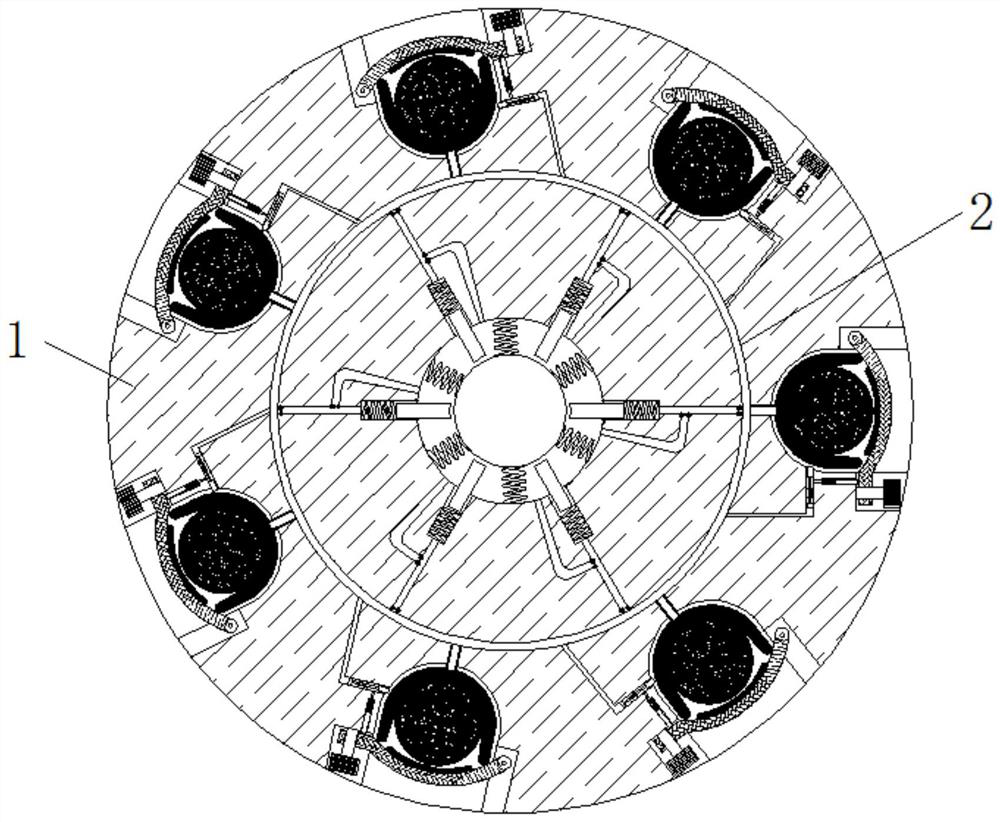
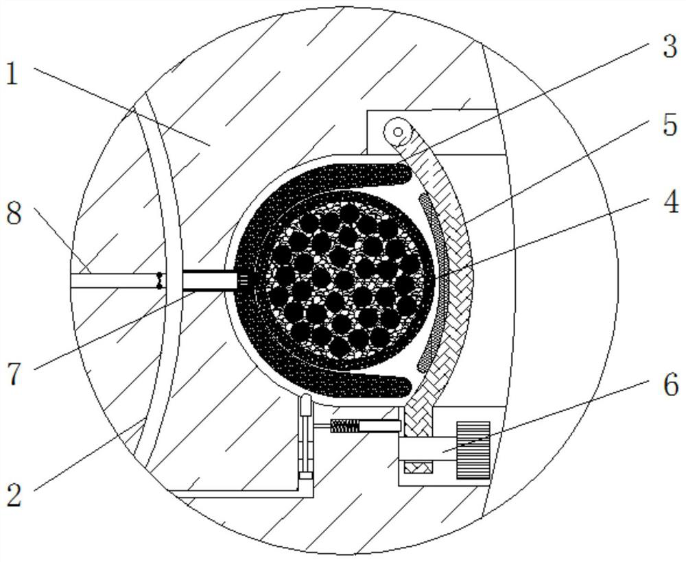
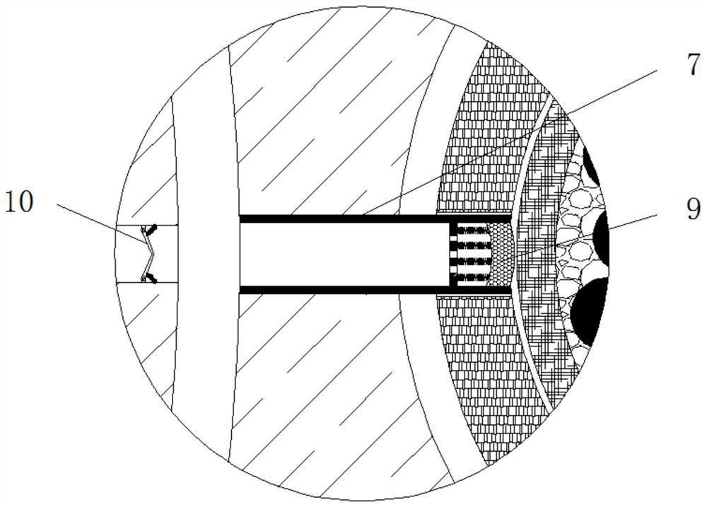
[0028] see Figure 1-6 , a cable fixing device for reducing cable wear, including a mounting plate 1, an annular tube 2 is installed inside the mounting plate 1, and a fitting strip 3 is secretly turned inside the mounting plate 1, and the fitting strip 3 is far away from the mounting plate 1 A cable 4 is installed on one side of the mounting plate 1, and the outer side of the mounting plate 1 is movably linked with a limit sleeve 5. A gasket is installed on t...


PUM


Abstract

The invention relates to the technical field of power systems. The invention further discloses a cable fixing device capable of reducing cable abrasion. The device comprises a mounting disc. An annular pipe is mounted in the mounting disc. An embedding strip is arranged in the mounting disc. A cable is mounted on the side, away from the mounting disc, of an embedding sleeve. A limiting sleeve is movably connected with the outer side of the mounting disc. A threaded rod is in threaded connection with the bottom of the limiting sleeve. An adjusting pipe is fixedly connected with the outer side of the annular pipe. The cable is fixed through the clamping effect between the limiting sleeve and the embedding strip. The limiting sleeve during a leftward moving process drives a pressing rod to move leftwards, and the air pressure of the left inner cavity of the pressing rod is increased. A top block at the top of a sliding rod generates pressure on the embedding strip under the action of theair pressure. The embedding strip is prevented from being influenced by factors such as gradual reduction of elasticity, aging and elastic deformation in a long-time contact fixing process. Certain pressure is always kept between the embedding strip and the cable.

Description

technical field [0001] The invention relates to the technical field of power systems, in particular to a cable fixing device for reducing cable wear. Background technique [0002] A cable refers to one or more insulated wire cores, and their respective covering layers, total protective layer and outer sheath. The cable can also have additional uninsulated conductors, whose main function is to transmit electric energy, information and Realize the conversion of electromagnetic energy. [0003] With the rapid development of my country's economy, power construction has developed by leaps and bounds. The current power equipment basically uses cables to supply power to it during use. The current cables generally use aerial wiring to transmit power during laying. However, the cables in the air will sway under the action of the wind, and the long-term swaying will cause serious cable wear and tear, and more seriously, the cable will be damaged. Contents of the invention [0004] ...

Claims


Application Information

Patent Timeline
Patent Type & Authority Patents(China)
IPC IPC(8): H02G7/05
CPCH02G7/05
Inventor 李思佳
Owner JIANGSU ELECTRIC POWER CO
Learn More