
Display panel, manufacturing method thereof and display device

A technology for display panels and manufacturing methods, applied in nonlinear optics, instruments, optics, etc., can solve problems such as low viewing angle contrast, uneven brightness, poor reliability, etc., and achieve the effect of reducing gray scale inversion and improving contrast

Active Publication Date: 2020-02-21
KUSN INFOVISION OPTOELECTRONICS
View PDF6 Cites 6 Cited by
  • Summary
  • Abstract
  • Description
  • Claims
  • Application Information

AI Technical Summary

Problems solved by technology

[0008] The present invention is to provide a display panel, a manufacturing method and a display device to solve the problem of low viewing angle contrast, uneven brightness, and reliability of liquid crystal display devices in the prior art. Poor and serious grayscale inversion

Method used


Image

  • Display panel, manufacturing method thereof and display device
  • Display panel, manufacturing method thereof and display device
  • Display panel, manufacturing method thereof and display device

Examples


Embodiment 1

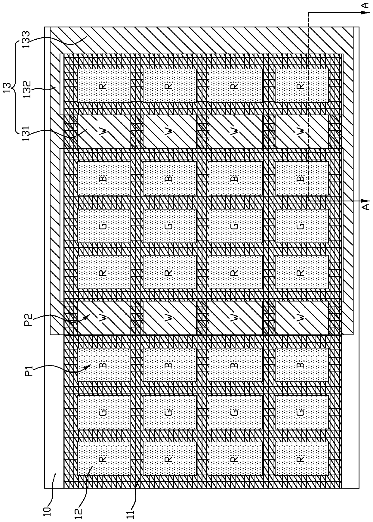
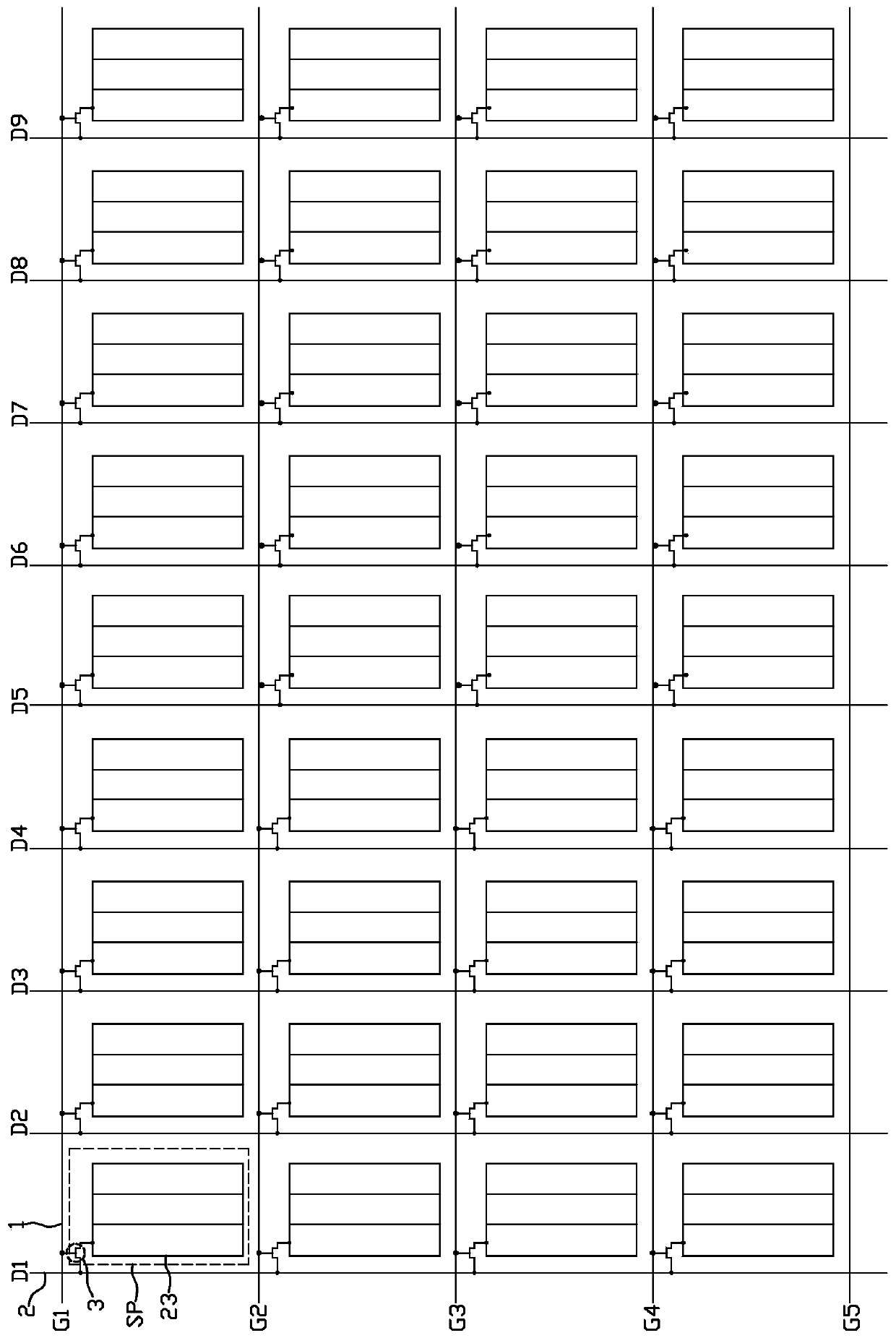
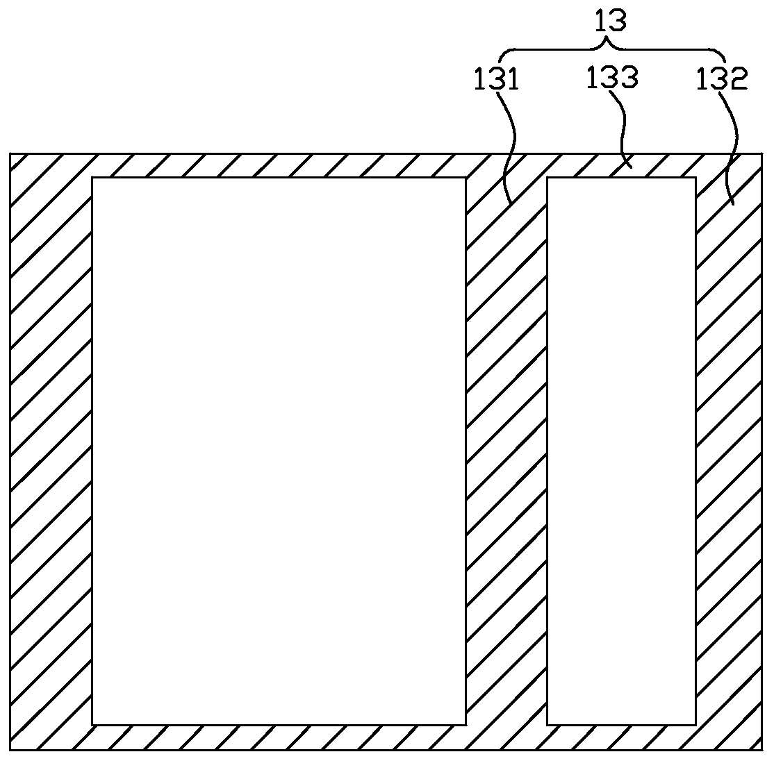
[0039] figure 1 is a schematic plan view of the color filter substrate in Embodiment 1 of the present invention, figure 2 is a schematic plan view of the array substrate in the present invention, image 3 is a schematic plan view of the view angle control electrode layer in Embodiment 1 of the present invention, Figure 4 It is the edge of the display panel in the initial state in the present invention figure 1 Schematic diagram of the cross-sectional structure in the A-A direction, Figure 5 It is the display panel in the present invention at a wide viewing angle along the figure 1 One of the schematic diagrams of the cross-sectional structure in the A-A direction, Image 6 It is the display panel in the present invention at a wide viewing angle along the figure 1 The second schematic diagram of the cross-sectional structure in the direction of A-A, Figure 7 It is the display panel in the present invention at a narrow viewing angle along the figure 1 Schematic diagra...

Embodiment 2

[0057] figure 2 is a schematic plan view of the array substrate in Embodiment 2 of the present invention, Figure 9 It is a schematic plan view of the color filter substrate in Embodiment 2 of the present invention. Such as Figure 9 As shown, the display panel provided by Embodiment 2 of the present invention is the same as Embodiment 1 ( Figures 1 to 7 The display panels in ) are basically the same, the difference is that in this embodiment, a plurality of blank areas P2 are arranged along the lateral direction, that is, along the extending direction of the scanning line 1 ( figure 2 ), the viewing angle control electrode 131 is a strip electrode extending along the lateral direction and covers a whole row of a plurality of blank areas P2. Every two rows of color regions P1 correspond to a row of blank regions P2 in a periodic arrangement. Of course, in other embodiments, three rows of color regions P1 correspond to a row of blank regions P2 in a periodic arrangement, ...

Embodiment 3

[0062] Figure 10 is a schematic plan view of the color filter substrate in Embodiment 3 of the present invention, Figure 11 is a schematic plan view of the array substrate in Embodiment 3 of the present invention. Such as Figure 10 with Figure 11 As shown, the display panel provided by Embodiment 3 of the present invention is the same as Embodiment 2 ( figure 2 with Figure 9) are basically the same, the difference is that in this embodiment, the length of the blank area P2 in the longitudinal direction is shorter than the length of the color area P1, that is, the length of the blank area P2 in the direction (vertical direction) of the data line 2 is shorter than the length of the color area P1. The length in the direction of the data line 2 of the area P1, each blank area P2 is aligned with the three color areas P1 in the direction of the scanning line 1 (horizontal direction), that is, the horizontal length of the blank area P2 and the total length of the three colo...


PUM

PropertyMeasurementUnit
thicknessaaaaaaaaaa

Abstract

The invention discloses a display panel, comprising a color film substrate, wherein the color film substrate is provided with a plurality of color areas, a plurality of blank areas and black matrixes,the black matrixes are used for separating the plurality of color areas from each other, separating the plurality of blank areas from each other, and separating the color areas from the blank areas,the color area is provided with a color resistance material therein, the blank area is in a transparent state, the color film substrate is also provided with a visual angle control electrode layer, the visual angle control electrode layer comprises a plurality of visual angle control electrodes covering the blank areas, and the visual angle control electrodes are directly formed on the surface ofthe color film substrate. According to the display panel of the invention, the visual angle control electrodes are directly formed on the surface of the color film substrate, so that the surfaces of the visual angle control electrodes are smooth, and a vertical electric field is formed by the visual angle control electrodes with public electrodes at the side of an array substrate, thereby improving a contrast ratio, in addition, wide / narrow visual angle switching is only achieved at the blank areas, thereby reducing gray scale reversal under a large visual angle. The invention also discloses adisplay device and a manufacturing method of the display panel.

Description

technical field [0001] The invention relates to the technical field of liquid crystal display, in particular to a display panel, a manufacturing method and a display device. Background technique [0002] With the continuous advancement of liquid crystal display technology, the viewing angle of the display has been expanded from about 120° to more than 160°. While enjoying the visual experience brought by the large viewing angle, people also hope to effectively protect commercial secrets and personal privacy. Avoid commercial loss or embarrassment caused by information leakage on the screen. [0003] The current display devices are gradually developing in the direction of wide viewing angles. Whether it is a mobile terminal application, a desktop display or a notebook computer application, in addition to the demand for a wide viewing angle, in many occasions, the display device is also required to have a wide viewing angle and a narrow viewing angle. Toggle function. [000...

Claims


Application Information

Patent Timeline
Patent Type & Authority Applications(China)
IPC IPC(8): G02F1/1335G02F1/1343G02F1/13
CPCG02F1/133512G02F1/133514G02F1/134309G02F1/1323
Inventor 朱梦青许雅琴贾本超何淑慧
Owner KUSN INFOVISION OPTOELECTRONICS
Learn More