


Quick Research
Generate reliable direction feasibility study reports for your R&D in just a few steps.

Technical Q&A
Discover and master advanced knowledge NOW. Basics, ideas, possibilities, all at once.

Find Solutions
As an expert in R&D theories, this can generate solutions to your technical problems instantly.

Evaluate Feasibility
Analyze your overall solution with one click, know your potential R&D risks in advance.

Monitor Landscape
Get weekly tech updates, stay abreast of the latest tech innovations and key insights.
Device and method for researching interfacial compatibility of a solid material
A technology of interfacial compatibility and solid materials, applied in measurement devices, analytical materials, surface/boundary effects, etc., can solve the problems of unsuitable laboratory scientific research, complicated structure and operation process of diffusion couple preparation devices, and achieve applicability The effect of extensive, simple structure and easy preparation
- Summary
- Abstract
- Description
- Claims
- Application Information
AI Technical Summary
Problems solved by technology
Method used
Image


Examples
Embodiment 1
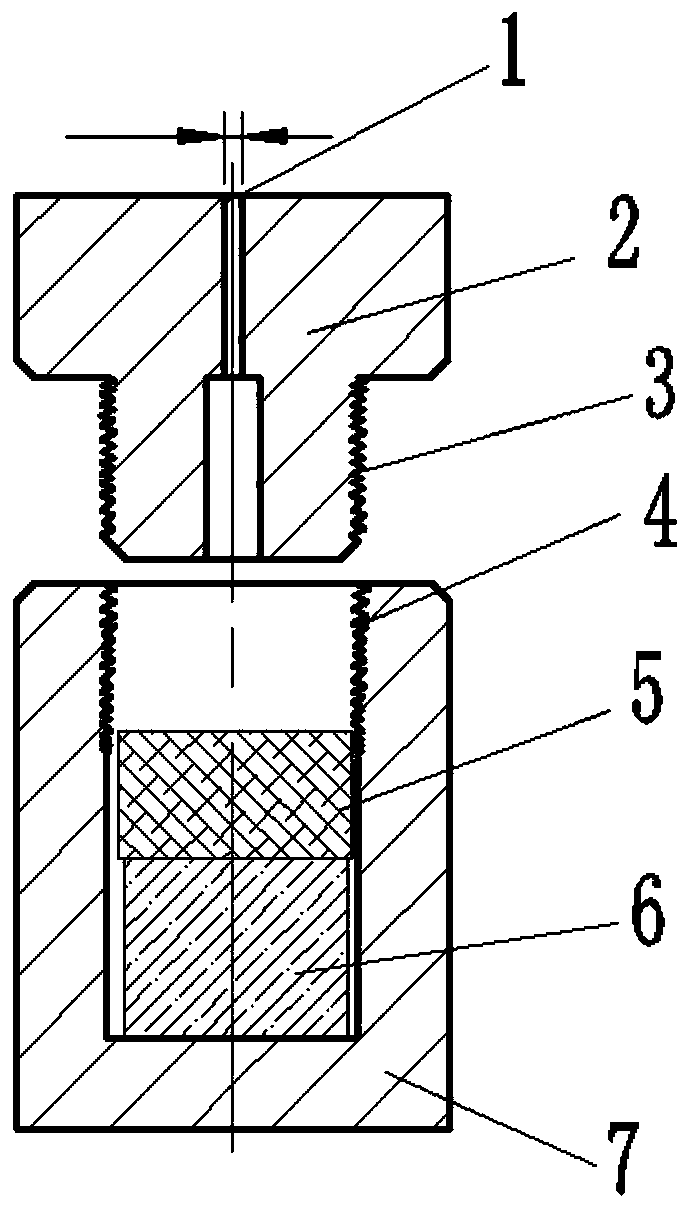
[0031] This embodiment provides a device for studying the interfacial compatibility of solid materials, which includes a material holder 7 and an end plug 2, which are made of stainless steel or high temperature resistant materials, and can be used according to the diffusion couple. Thickness selects the bearing tube 7 of corresponding height, and the bearing tube 7 adopts the cylindrical structure that the bottom end is closed and the top is open. The object holding cylinder 7 is used to accommodate the solid material I5 and solid material II6 for preparing the diffusion couple. After the end plug 2 and the top open end of the object holding cylinder 7 are connected by threads, they are fixed by circular seam welding, and the end plug 2 is used The solid material I5 and the solid material II6 are pressed tightly, so that the interface between the solid material I5 and the solid material II6 is pressed together; the end plug 2 is provided with a micropore 1 for vacuuming the in...
Embodiment 2
[0033] Further improvement on the basis of Example 1, the end plug 2 includes a horizontal section and a vertical section, the horizontal section is a circular plate structure with the same outer diameter as the outer diameter of the object holder 7, the vertical section is a cylindrical straight rod structure, and the horizontal section and The vertical sections are arranged perpendicularly to each other, and have a T-shaped structure on the axial section of the vertical sections. The free end of the vertical section of the end plug 2 is provided with an external thread, and the top open end of the container 7 is provided with an internal thread, and the free end of the vertical section of the end plug 2 is screwed into the bearing through an internal thread and an external thread. In the object cylinder 7, until the end face of the vertical section is pressed and contacted with the solid material I5; a chamfering structure is arranged on the outer edge of the circular plate s...
Embodiment 3
[0035] Based on the device provided in Example 2, this example provides a method for studying the interfacial compatibility of solid materials, and the specific steps are as follows:
[0036] Step 1, put the solid material I and solid material II to be studied into the container,
[0037] Step 2, one end of the end plug is screwed into the object container from the open end of the object container through threaded connection, and the end surface of the end part inserted into the object container by the end plug is pressed to fasten the solid material I and the solid material II, and the solid material I and solid material II are compressed between the lower end surface of the end plug and the inner bottom surface of the container, so that the interface between the solid material I and the solid material II maintains a positive pressure fit; then the container and the end are connected by circular seam welding. The gap in the circumferential direction of the plug realizes the v...
PUM
 Abstract
Description
Claims
Application Information
 - R&D Engineer
- R&D Manager
- IP Professional
- Industry Leading Data Capabilities
- Powerful AI technology
- Patent DNA Extraction
Browse by: Latest US Patents, China's latest patents, Technical Efficacy Thesaurus, Application Domain, Technology Topic, Popular Technical Reports.
© 2024 PatSnap. All rights reserved.Legal|Privacy policy|Modern Slavery Act Transparency Statement|Sitemap|About US| Contact US: help@patsnap.com