Detachable locating and mounting rack for ceiling board

A technology for positioning installation and ceiling suspension, which is applied in the direction of house structure support, house structure support, construction, etc., can solve the problems of inconvenient disassembly, low installation efficiency, and difficult installation, and achieves reduction of installation difficulty, improvement of installation efficiency, and reduction of labor. amount of effect

Active Publication Date: 2020-02-21
安徽福瑞尔铝业科技有限公司
View PDF9 Cites 4 Cited by
  • Summary
  • Abstract
  • Description
  • Claims
  • Application Information

AI Technical Summary

Problems solved by technology

But the installation is difficult, the installation efficiency is low, and it is not easy to disassemble

Method used


Image

  • Detachable locating and mounting rack for ceiling board
  • Detachable locating and mounting rack for ceiling board
  • Detachable locating and mounting rack for ceiling board

Examples


Embodiment 1

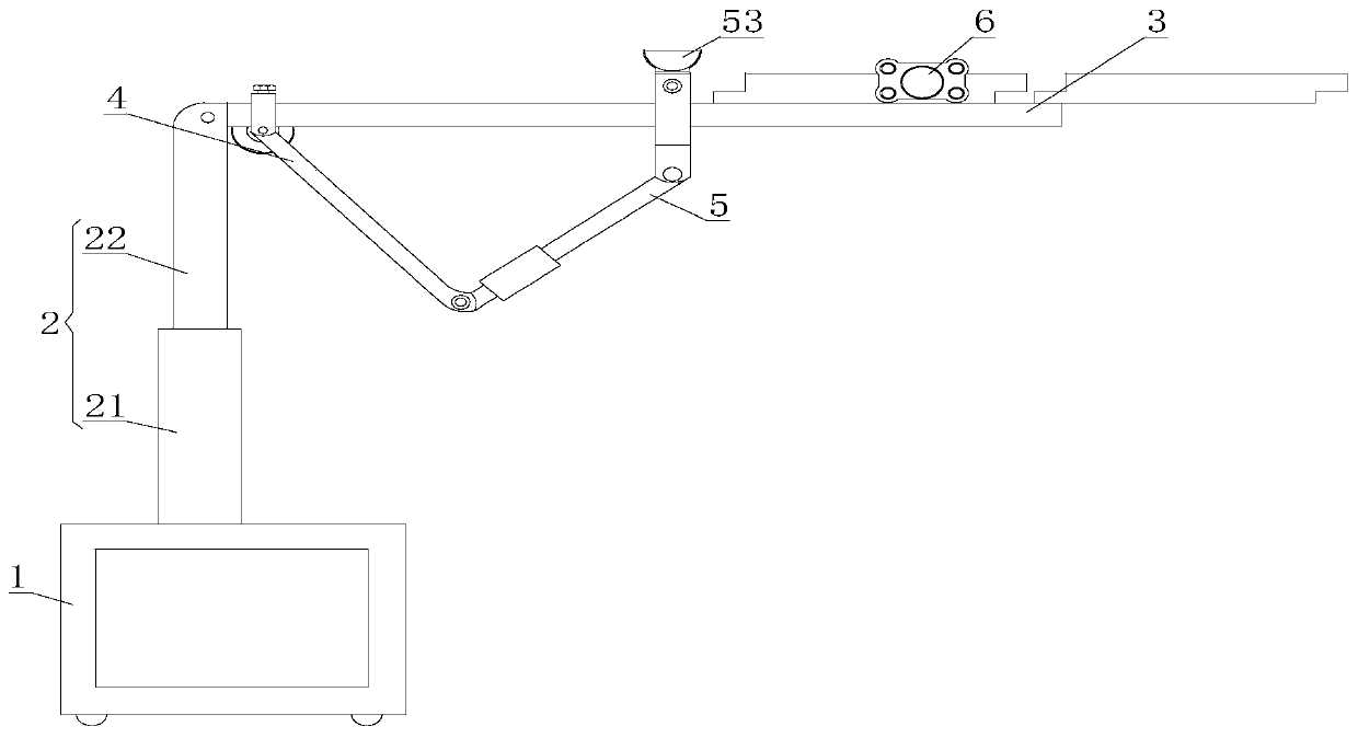
[0027] see figure 1 , a detachable positioning installation frame for ceiling panels, including a base 1, a lifting rod 2, an end plate 3, a first rocker arm 4, a second rocker arm 5 and a pushing mechanism 6, and the upper surface of the base 1 is fixedly connected with a lifting rod 2. The lifting rod 2 includes a cylinder base 21 and a cylinder rod 22. The cylinder base 21 is movably connected to the cylinder rod 22. The lower end of the cylinder base 21 is connected to the base 1 through bolt locking, and the upper end of the cylinder rod 22 is connected to the cylinder through bolt locking. The rod 22, the cylinder seat 21 in the lifting rod 2 drives the cylinder rod 22 to rise, and drives the end plate 3 to rise as a whole, until the upper surface of the end plate 3 abuts against the lower surface of the installed ceiling plate, and the upper end of the lifting rod 2 is fixedly connected There is an end plate 3, and a push mechanism 6 is installed on the upper surface of...

Embodiment 2

[0032] see Figure 8 The difference between the second embodiment and the first embodiment is that the cross section of the tooth plate 32 is circular, and the ring sleeve 52 includes a third plate body 526, a shaft hole 527 and a ball 528. The shaft hole 527 is movably connected with a ball 528 inside the shaft hole 527, and the ball 528 is rollingly connected with the gear plate 32 to reduce friction.

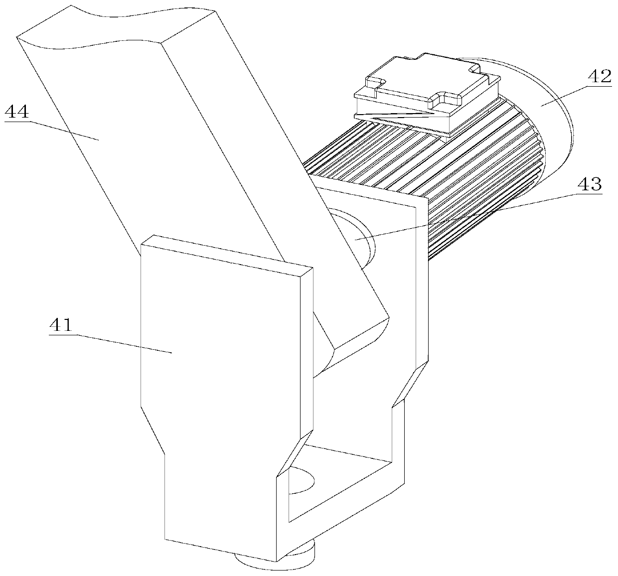
[0033] Working principle: Place the ceiling plate on the right end tooth plate 32 of the end plate 3, the cylinder seat 21 in the lifting rod 2 drives the cylinder rod 22 to rise, and drives the end plate 3 to rise as a whole until the upper surface of the end plate 3 abuts on the already The lower surface of the installed ceiling plate realizes the vertical movement of the end plate 3 in the direction of the Z axis; the rotation of the motor 42 drives the rotation of the rotation shaft 43, and the rotation of the rotation shaft 43 drives the rotation of the first rocker 44, an...


PUM


Abstract

The invention discloses a detachable locating and mounting rack for a ceiling board. The detachable locating and mounting rack comprises a base, a lifting rod, an end plate, a first rocking arm, a second rocking arm and a pushing mechanism. The lifting rod is fixedly connected to the upper surface of the base. The end plate is fixedly connected to the upper end of the lifting rod. The pushing mechanism is mounted on the upper surface of the right end of the end plate. The second rocking arm is in sliding connection to the middle of the end plate. The first rocking arm is connected to the leftend of the end plate in a bolt locking manner. The first rocking arm comprises a U-shaped plate, a motor, a rotary shaft and a first rocking bar. The U-shaped plate is fixedly connected with the end plate through a bolt. The U-shaped plate is rotationally connected with the rotary shaft through a bearing. The rotary shaft is connected with the motor. The first rocking bar is fixedly connected to the middle of the rotary shaft. The ceiling board is mounted through the motor and an air cylinder in a process manner, mounting difficulty is reduced, mounting efficiency is improved, mounting precision is improved, and the ceiling board can be dismounted through a silica gel suction cup.

Description

technical field [0001] The invention relates to the technical field of ceiling installation frames, in particular to a detachable positioning installation frame for ceiling panels. Background technique [0002] Suspended ceiling refers to a kind of decoration on the top decoration of the living environment of the house. Simply put, it refers to the decoration of the ceiling, which is one of the important parts of interior decoration. The suspended ceiling has the functions of heat preservation, heat insulation, sound insulation and sound absorption, and it is also the hidden layer of electrical, ventilation and air conditioning, communication and fire protection, alarm pipeline equipment and other projects. Domestic outfit condole is the common link in domestic outfit. The suspended ceiling is classified differently according to the material of the decorative board. Ceiling decoration materials are the main basis for distinguishing the name of the ceiling, mainly includin...

Claims


Application Information

Patent Timeline
IPC IPC(8): E04G1/24E04G1/18E04F21/18
CPCE04F21/18E04F21/1872E04G1/18E04G1/24
Inventor 刘露于亚民韦茂忠何世发
Owner 安徽福瑞尔铝业科技有限公司
Why Eureka
Try Eureka