Positioning and rotating mechanism for reel in textile equipment

A technology for positioning and rotating textile equipment, which is applied in textiles, looms, textiles, and papermaking. It can solve the problems of lack of adjustment devices, difficult position adjustment, and falling of installation positioning devices, so as to improve safety performance, increase the scope of application, The effect of preventing collision

Active Publication Date: 2020-02-21
新昌县衣锦纺织机械有限公司
View PDF6 Cites 3 Cited by
  • Summary
  • Abstract
  • Description
  • Claims
  • Application Information

AI Technical Summary

Problems solved by technology

[0003] The existing wire wheel positioning device is usually a fixed device, which is difficult to achieve precise and intelligent position adjustment, which leads to a lower application range of the textile machine; the existing positioning device of the textile machine lacks a protective structure, and once the power or air is cut off, it will Cause the installation and positioning device to fall, which will cause a major safety accident; the lack of adjustment device after the positioning is completed, resulting in insufficient tension of the weaving thread, which will affect the textile quality
[0004] To this end, a positioning and rotating mechanism for the thread wheel in textile equipment is provided to solve the problems of the applicability, safety and adjustment device of the positioning device

Method used


Image

  • Positioning and rotating mechanism for reel in textile equipment
  • Positioning and rotating mechanism for reel in textile equipment
  • Positioning and rotating mechanism for reel in textile equipment

Examples


Embodiment Construction

[0026] The following will clearly and completely describe the technical solutions in the embodiments of the present invention with reference to the accompanying drawings in the embodiments of the present invention. Obviously, the described embodiments are only some, not all, embodiments of the present invention. Based on the embodiments of the present invention, all other embodiments obtained by persons of ordinary skill in the art without making creative efforts belong to the protection scope of the present invention.

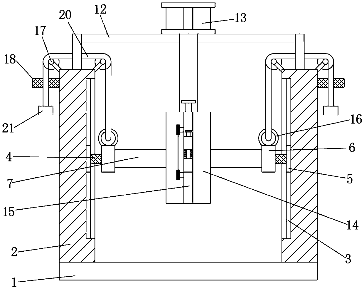
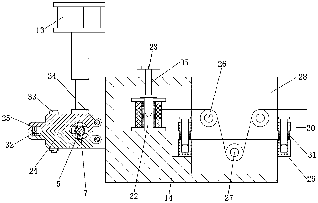
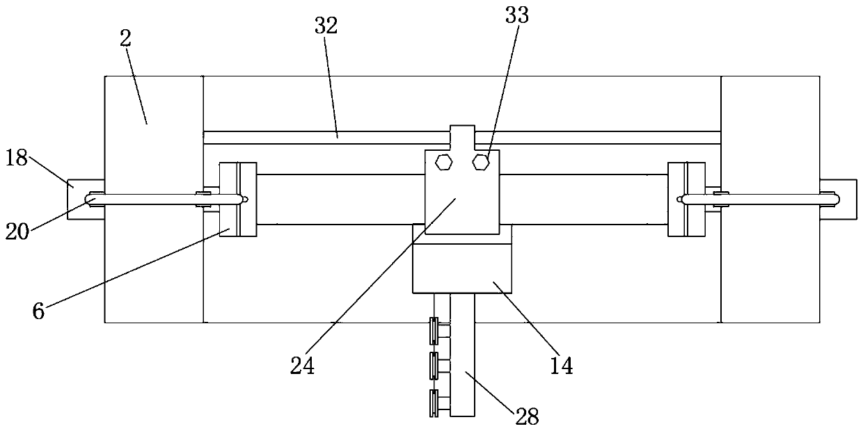
[0027] see Figure 1 to Figure 5 , the present invention provides a technical solution:

[0028] A positioning and rotating mechanism for thread wheels in textile equipment, comprising a base 1, support columns 2 are vertically welded to the left and right ends of the upper end surface of the base 1, and chute 3 is provided on the inner side of the adjacent left and right support columns 2, and the chute 3 The inner cavity of the horizontal screw rod 4 is ins...


PUM


Abstract

The invention relates to the technical field of positioning of a reel for textile equipment, in particular to a positioning and rotating mechanism of a reel for textile equipment. The positioning androtating mechanism of the reel for the textile equipment comprises a base, wherein supporting columns are vertically welded to the left end and the right end of the upper end face of the base, slidinggrooves are formed in the inner sides of the left supporting column and the right supporting column which are adjacent to each other, supports are transversely installed between the upper end faces of the left supporting column and the right supporting column which are adjacent, baffles are vertically welded to the upper ends of the outer end faces of the two adjacent supporting columns, and a transverse screw rod is arranged in the cavity of each sliding groove. The positioning and rotating mechanism of the reel for the textile equipment has the beneficial effects that a positioning frame isdriven to move up and down through cooperation of the sliding grooves and cylinders, left and right adjustment of the positioning frame is realized through cooperation of a screw rod and internal thread, the multi-degree-of-freedom position adjustment of the positioning frame is further realized, and the application range of the positioning frame is improved; due to cooperation of a steel wire pull rope and the baffles, the screw rod is stretched upwards, when the cylinders fail, the steel wire pull rope is used for protecting the positioning frame, the positioning frame is prevented from colliding with equipment, and the safety performance is improved.

Description

technical field [0001] The invention relates to the technical field of positioning wire wheels for textile equipment, in particular to a positioning and rotating mechanism for wire wheels in textile equipment. Background technique [0002] In the weaving process, the wire wheel in the weaving machine needs to be precisely positioned to ensure that the quality and size of the woven clothes meet the requirements. [0003] The existing wire wheel positioning device is usually a fixed device, which is difficult to achieve precise and intelligent position adjustment, which leads to a low application range of the textile machine; the existing positioning device of the textile machine lacks a protective structure, once the power or air is cut off, it will Cause the installation and positioning device to fall, and then cause a larger safety accident; lack of adjustment device after the positioning is completed, resulting in insufficient tension of the weaving thread, which in turn a...

Claims


Application Information

Patent Timeline
IPC IPC(8): D03D47/34
CPCD03D47/34D03D47/345
Inventor 龙云凤
Owner 新昌县衣锦纺织机械有限公司
Why Eureka
Try Eureka