
Patsnap Eureka
For R&D, Patsnap Eureka makes reading and utilizing patents & technical documents easy.
Patsnap Eureka AIR
Designed for self-driven R&D workflows. Generate viable solutions, solve complex R&D challenges, empower your innovation with AI.

Patsnap Eureka Materials
Designed for material experts only. Revolutionize your material R&D, from search, analyze, to developing new materials.

TechResearch
Generate reliable direction feasibility study reports for your R&D in just a few steps.

TechSeek
Discover and master advanced knowledge NOW. Basics, ideas, possibilities, all at once.

TechMind
As an expert in R&D Theories, TechMind can generates customized viable solutions instantly.

TechRisk
Analyze your overall solution with one click, know your potential R&D risks in advance.

TechMonitor
Get weekly tech updates, stay abreast of the latest tech innovations and key insights.
A kind of antidandruff shampoo and its preparation system and processing method
A preparation system, shampoo technology, applied in the direction of manufacturing tools, pharmaceutical formula, hair care, etc., can solve the problems of not being able to beat the raw materials to produce juice, extract the original solution, etc.
- Summary
- Abstract
- Description
- Claims
- Application Information
AI Technical Summary
Problems solved by technology
Method used
Image

Examples
specific Embodiment approach 1
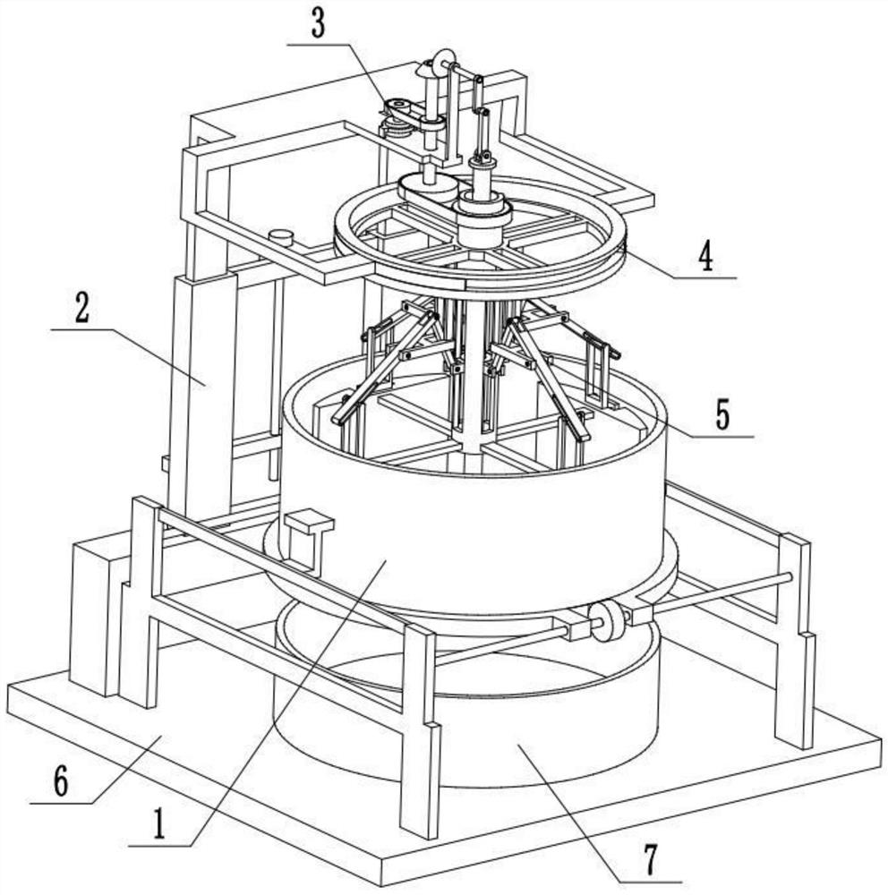
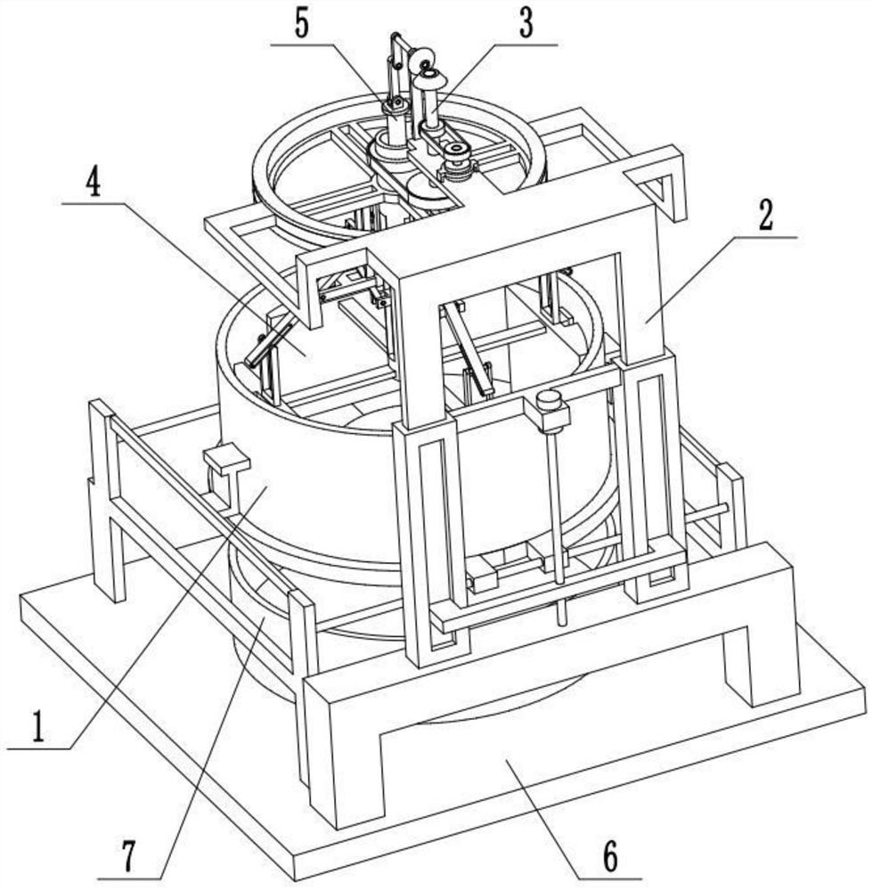
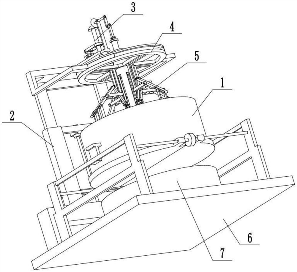
[0033] Combine below Figure 1-10 Describe this embodiment, a preparation system for anti-dandruff shampoo, including a material extrusion cylinder assembly 1, a lifting adjustment mechanism 2, a material rotating extrusion mechanism 3, a power output mechanism 4, an extrusion driving mechanism 5, a base 6 and a material A collection box 7, the material extrusion cylinder assembly 1 is fixedly connected to the base 6, the material collection box 7 is placed on the base 6, the material collection box 7 is located below the material extrusion cylinder assembly 1, and the lifting adjustment mechanism 2 is fixedly connected to Behind the material extrusion cylinder assembly 1, the material rotary extrusion mechanism 3 is arranged on the upper end of the lifting adjustment mechanism 2, the upper end of the power output mechanism 4 is arranged on the lifting adjustment mechanism 2, and the lower end of the power output mechanism 4 is located on the material extrusion cylinder assembl...
specific Embodiment approach 2
[0035] Combine below Figure 1-10 To illustrate this embodiment, the material extrusion cylinder assembly 1 includes a side frame 1-1, a guide rod 1-2, a bidirectional screw 1-3, a bottom plate 1-4, a screw ring 1-5, and a circular cylinder 1 -6 and the fixed frame 1-7; the guide rod 1-2 is fixedly connected to the rear end of the two side frames 1-1, and the two-way screw rod 1-3 is rotated and connected to the front ends of the two side frames 1-1. The rear ends of the two bottom plates 1-4 are symmetrically slidably connected to the guide rod 1-2, and the front ends of the two bottom plates 1-4 are connected to the two ends of the two-way screw rod 1-3 through thread fit, and the screw ring 1-5 is fixedly connected. In the middle of the two-way screw 1-3, the two ends of the circular tube 1-6 are respectively fixedly connected to a fixed frame 1-7, and the two fixed frames 1-7 are respectively fixedly connected to the two side frames 1-1, and the circular The bottom surfac...
specific Embodiment approach 3
[0037] Combine below Figure 1-10 To illustrate this embodiment, the lifting adjustment mechanism 2 includes a portal frame 2-1, a rectangular hollow column 2-2, a rectangular through slot I2-3, a slide bar 2-4, a U-shaped plate 2-5, and a drive motor I2 -6, lead screw 2-7, top frame plate 2-8, shift fork 2-9, horizontal shaft frame plate 2-10 and vertical shaft frame plate 2-11; portal frame 2-1 is fixedly connected to base 6 On the top, two rectangular hollow columns 2-2 are fixedly connected to the portal frame 2-1, and a rectangular through-slot I2-3 is respectively arranged at the rear ends of the two rectangular hollow columns 2-2, and the two ends of the U-shaped plate 2-5 The two ends of the U-shaped plate 2-5 are respectively fixedly connected to a sliding rod 2-4, and the two sliding rods 2-4 are respectively slidingly fitted and connected to two rectangular hollow slots. In the column 2-2, the driving motor I2-6 is fixedly connected between two rectangular hollow c...
PUM
 Abstract
Description
Claims
Application Information
 - R&D Engineer
- R&D Manager
- IP Professional
- Industry Leading Data Capabilities
- Powerful AI technology
- Patent DNA Extraction
Browse by: Latest US Patents, China's latest patents, Technical Efficacy Thesaurus, Application Domain, Technology Topic, Popular Technical Reports.
© 2024 PatSnap. All rights reserved.Legal|Privacy policy|Modern Slavery Act Transparency Statement|Sitemap|About US| Contact US: help@patsnap.com