Fog gun machine control system
A technology of control system and fog cannon, which is applied in the direction of liquid injection device, dispersed particle separation, spray device, etc. It can solve the problems of unable to detect the surrounding air, unable to collect data, and affect the service life of the fog cannon, so as to improve the air quality , avoid corrosion, and facilitate adjustment
- Summary
- Abstract
- Description
- Claims
- Application Information
AI Technical Summary
Problems solved by technology
Method used
Image
Examples
Embodiment 1
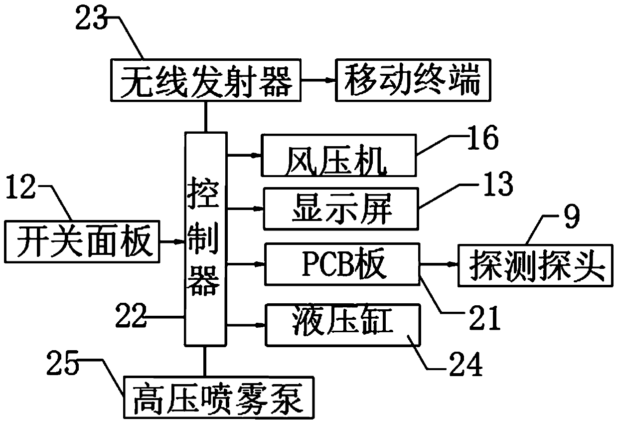
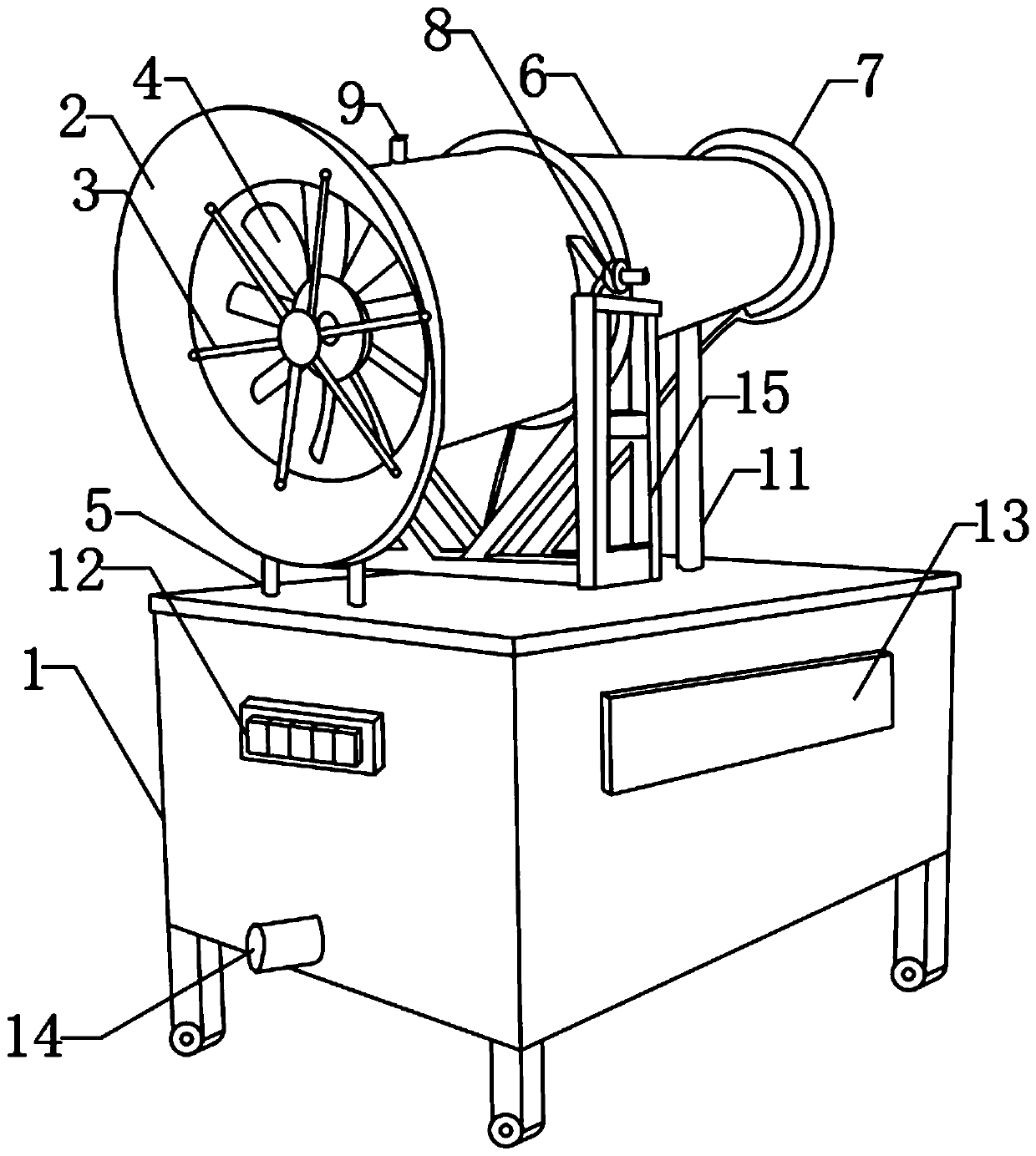
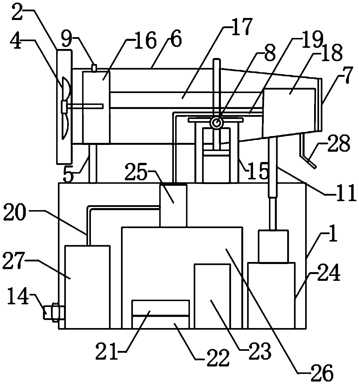
[0027] Such as Figure 1-5 As shown, a fog cannon machine control system includes an installation box 1, a support frame 15 and a cavity 6, a support frame 15 is fixedly installed in the middle of the top of the installation box 1, and a rotating shaft 8 is fixedly installed on the top of the support frame 15, and the rotating shaft 8 Installed through the middle of the cavity 6.
[0028] One side top of installation box 1 is fixedly installed switch panel 12, and the front of installation box 1 is fixedly installed with display screen 13, and the four corners of installation box 1 bottom are all fixedly installed with legs, and the bottom of each leg is all fixedly installed with universal wheel.
[0029] One side inside the fixed box 26 is fixedly installed with a controller 22 , the top of the controller 22 is fixedly installed with a PCB board 21 , and the other side inside the fixed box 26 is fixedly installed with a wireless transmitter 23 .
[0030] The surface of the...
Embodiment 2
[0034] Such as Figure 1-5 As shown, a fog cannon machine control system includes an installation box 1, a support frame 15 and a cavity 6, a support frame 15 is fixedly installed in the middle of the top of the installation box 1, and a rotating shaft 8 is fixedly installed on the top of the support frame 15, and the rotating shaft 8 Installed through the middle of the cavity 6.
[0035] One side top of installation box 1 is fixedly installed switch panel 12, and the front of installation box 1 is fixedly installed with display screen 13, and the four corners of installation box 1 bottom are all fixedly installed with legs, and the bottom of each leg is all fixedly installed with universal wheel.
[0036] One side of installation box 1 inside is fixedly installed with hydraulic cylinder 24, and the hydraulic rod of hydraulic cylinder 24 links to each other with the bottom end of second pole 11, and the middle part of installation box 1 is fixedly installed with fixed box 26,...
Embodiment 3
[0043] Such as Figure 1-5 As shown, a fog cannon machine control system includes an installation box 1, a support frame 15 and a cavity 6, a support frame 15 is fixedly installed in the middle of the top of the installation box 1, and a rotating shaft 8 is fixedly installed on the top of the support frame 15, and the rotating shaft 8 Installed through the middle of the cavity 6.
[0044] One side of the top of the installation box 1 is fixedly equipped with two first poles 5, and the tops of the two first poles 5 are hinged with an installation cover 2, and one side of the installation cover 2 is fixedly installed with a protective net 3, and the installation cover 2 is fixed. Installed on one side of the cavity 6, the other side of the cavity 6 is fixedly installed with a nozzle 7, the bottom end of the nozzle 7 is fixedly installed with a second pole 11, and the second pole 11 is installed through the side of the installation box 1. top.
[0045] One side top of installat...
PUM
 Abstract
Description
Claims
Application Information
 - R&D
- Intellectual Property
- Life Sciences
- Materials
- Tech Scout
- Unparalleled Data Quality
- Higher Quality Content
- 60% Fewer Hallucinations
Browse by: Latest US Patents, China's latest patents, Technical Efficacy Thesaurus, Application Domain, Technology Topic, Popular Technical Reports.
© 2025 PatSnap. All rights reserved.Legal|Privacy policy|Modern Slavery Act Transparency Statement|Sitemap|About US| Contact US: help@patsnap.com


